13
NOTE: The elements on UK models are to
240V specification and will give a lower kW
rating if the voltage supply is below 240V.
7
Continued
SECTION
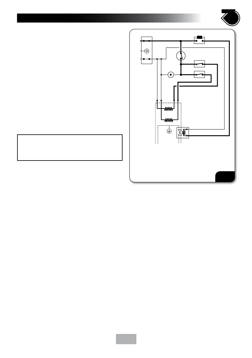
• (fig.12) shows a schematic wiring diagram.
IMPORTANT: When connecting the cable fully
tighten the terminal block screws and make sure
that no cable insulation is trapped under the
screws. Loose connections can result in cable
overheating.
NOTE: The supply cable earth conductor must
be sleeved. The outer sheath of the supply cable
must be stripped back to the minimum.
• The use of connections within the unit or
other points in the shower circuit to supply
power to other equipment i.e. extractor fans,
pumps etc. will invalidate the guarantee.
• DO NOT switch on the electricity supply
until the shower cover has been fitted.
1.
2.
3.
4.
5.
6.
7.
Terminal block
Start/Stop switch
Power selector
Microswitch
Solenoid valve
Thermal cut-out (main)
Neon - power
Element
3
4
5
7
L
N
E
inlet
outlet
1
3
7
6
Fig.12

 Loading...