15
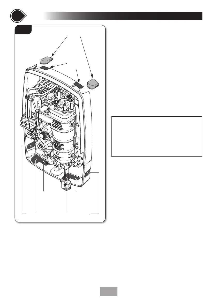
The backplate has removable top trims (top left
and top right) that may be used for pipe entry
and two additional sections (top left and top
right) that may ONLY be used as a ‘cut out’ for
top electrical cable entry (fig.9).
The showers bottom trimplate has also been
designed with four ‘cut out’ bottom/side water
pipe access points and two ‘cut out’ electrical
cable access points (fig.9).
• Decide which entry points are to be used
for the water pipe entry and electrical cable
entry.
• Once chosen, remove either the appropriate
trim or if ‘cut outs’ have been chosen,
remove them using a junior hacksaw, file or
appropriate knife.
Fitting Procedure
• Turn off water supply either at the mains
stopvalve or the isolating stopvalve.
• Temporarily connect the mains water supply
to the inlet of the shower using a 15mm x
15mm compression fitting.
• Use the backplate as a template making sure
it is level and mark the fixing holes (fig.10).
The top and one of the bottom two fixing
holes should be sufficient to hold the shower.
• Remove the unit from the wall. Drill and
plug the wall. An appropriate drill bit should
be used. If the wall is plasterboard or a soft
building block, appropriate wall plugs should
be fitted.
• Screw the top fixing screw into position
leaving the base of the screw head
protruding 6mm out from the wall.
• Hook the backplate over the top screw and
fit the bottom fixing screws into position,
Fig.9
Top pipe trims
7
Continued
SECTIONSECTION
PLEASE NOTE: NONE of the 'cut outs' are
designed to 'snap out'. ONLY a junior hacksaw, file,
or suitable knife should be used. Excessive damage
to the backplate or lower trimplate outside the
prescribed areas marked in (fig.9) may invalidate
product specifications and warranty.
Top cable
‘Cut out’
entry points
‘Cut out’ Pipe entry points - on trimplate
‘Cut out’
Cable
entry point
‘Cut out’
Cable
entry point
 Loading...