18
NOTE: The elements on UK models are to
240V specification and will give a lower kW
rating if the voltage supply is below 240V.
7
Continued
SECTIONSECTION
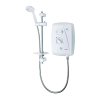
• Fig.12 shows a schematic wiring diagram.
IMPORTANT: When connecting the cable fully
tighten the terminal block screws and make sure
that no cable insulation is trapped under the
screws. Loose connections can result in cable
overheating.
NOTE: The supply cable earth conductor must
be sleeved. The outer sheath of the supply cable
must be stripped back to the minimum.
• The use of connections within the unit or
other points in the shower circuit to supply
power to other equipment i.e. extractor fans,
pumps, etc. will invalidate the guarantee.
• DO NOT switch on the electricity supply
until the shower cover has been fitted.
FITTING THE COVER
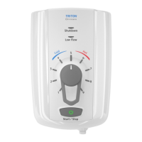
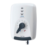
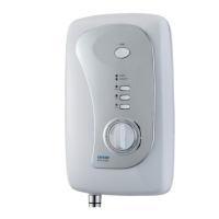
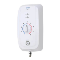
Figs 13, 14, 15 and 16 on page 19 show the
correct control knob position when replacing the
cover.
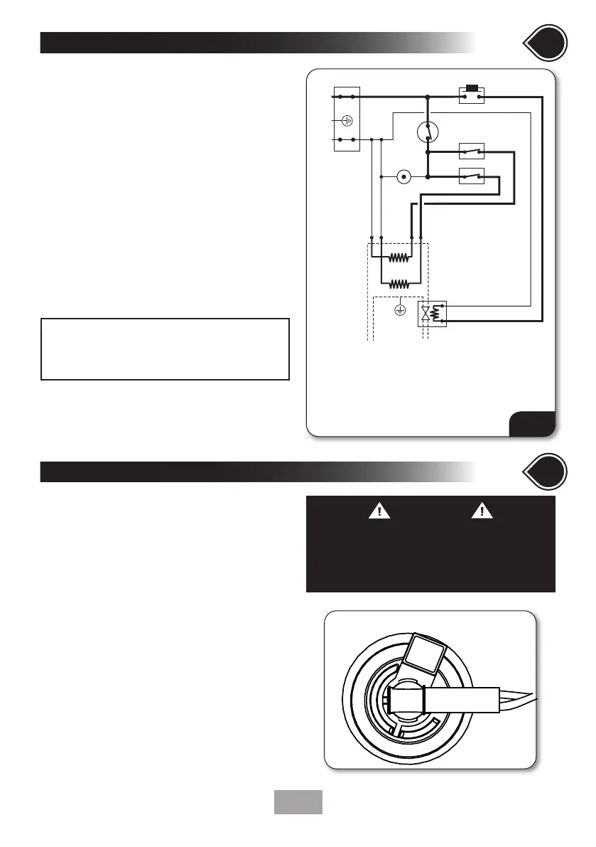
• Clip the neon into the back of the Start/Stop
assembly on the inside of the cover in the
correct orientation (shown below, right.)
• Check to ensure that the wiring is not
trapped and replace the cover squarely to
the backplate and guide into position so that
the knobs locate correctly into the splined
spindles.
• Should any difficulty arise, recheck the
points above.
• While applying slight pressure to the cover,
secure in position with the retaining screws.
• Fit the Riser Rail and Kit (see kit
instructions).
Installation - FITTING THE COVER
8
check list
SECTION SECTION
1.
2.
3.
4.
5.
6.
7.
Terminal block
Start/Stop switch
Power selector
Microswitch
Solenoid valve
Thermal cut-out (main)
Neon - power
Element
3
4
5
7
L
N
E
inlet
outlet
1
3
7
6
Fig.12
WARNING
COVER RETAINING SCREWS
ONLY the SUPPLIED SCREWS should be
used. The use of non supplied screws WILL
invalidate product specications & warranty.
CORRECT NEON FITTING ORIENTATION
 Loading...