Recheck
all bolts and nuts are
tightened securely
before using the machine
7815-7
ASSEMBLY STEPS
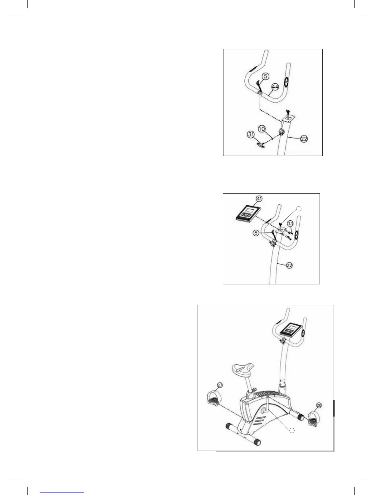
STEP 04
• Attach the Handlebar (44) to Upright Tube (22)
with M8 Washer (10) and T Knob (31)
CAUTION:
Ensure that cables are not damaged
during assembly or when tightening screws.
STEP 05
• Attach the Pulse Wire (5) and Computer Upper
Cable (16) to the Computer (41)
• Attach the Computer (41) to the Upright Tube (22)
with four M5*15 Screw (33)
CAUTION:
Ensure that cables are not damaged
during assembly or when tightening screws.
STEP 06
• Insert the Left Pedal (27) and Right Pedal (26) into
the Crank (20)
16
20