1574-10
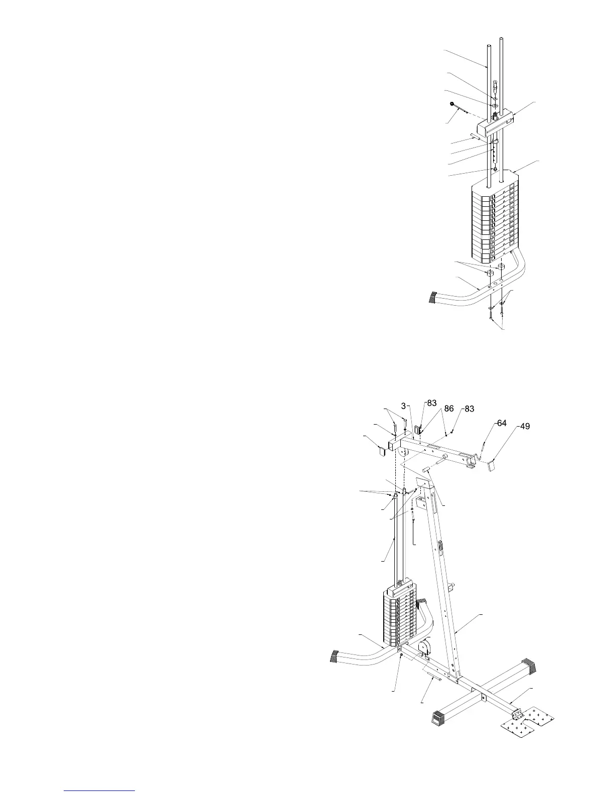
STEP 2
• Install two Chrome Tubes (9) into holes of Rear Base Frame (1) using
2-3/8”X1” Hex Bolts (82) 2-3/8” Washers (86).
• Slide two Round Donuts (48) down Chrome Tubes (9).
• Slide 14 pcs Weight Plates (26) and Weight Selection Rod (28) down
Chrome Tubes (9)
• Slide Top Weight (27) down.
• Attach Plastic Bushing (35) to Weight Selection Rod (28) with Pin (105).
• Place T3.0xø47xø26 Washer (89) and T3.0xø13xø32 Washer (106) onto
the hole of Top Weight (27).
• Attach Nut end of Top Cable to Weight Selection Rod (28).
• Install black Ball Pin (41) to Weight Selection Rod (28) as shown.
STEP 3
• Attach two Steel Bushings (59) to top of Chrome Tubes (9)
using 2- M6x8mm Screws (91)
• Attach Top Frame (3) to top of Chrome Tube (9) using
2-3/8”X1” Hex Bolts (82) 2-3/8” Washers (86).
• Attach Top Frame (3) to Front Upright (7) using
1-3/8”X3-3/4” hex bolt (74) 1-3/8”X2-7/8” Hex Bolt (76)
4-3/8” Washers (86) 2-3/8” Locknuts (83).
• Attach Single Pulley Bracket (100) to Main Base Frame (2)
using 1-3/8”X4” Hex Bolt (95) 1-3/8” Locknut (83).
• Push two Long Handle Grips (58) onto each end of Shaft of
Top Frame (3).
• Push two Little Covers (64) onto each end of Hook of Top
Frame (3).
ASSEMBLY STEPS
82
86
26
27
1
35
41
105
48
9
89
94
28
106
58
7
82
86
74
86
76
2
49
95
83
100
1
59
91
9