1574-9
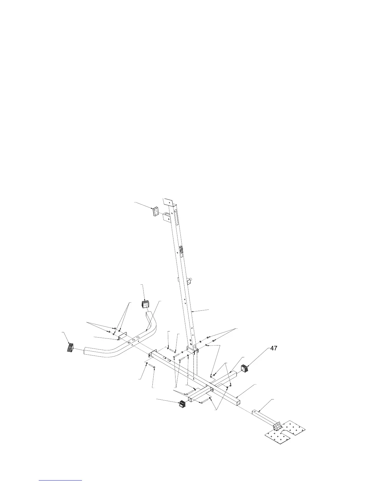
STEP 1
• Push Square End Cap (47) onto ends of Rear Base Frame (1) and Base Frame (8). Attach Connect Plate (36) and
Rear Base Frame (1) to Main Base Frame (2) using 2- 3/8”X3” hex bolts (75) 4-3/8” Washers (86) 2-3/8” Locknuts
(83).
• Plug 50x75mm Square Plug (49) onto Front Upright (7). Insert Foot Plate (10) to Main Base Frame (2).
• Attach Two Base Frame (8) to Main Base Frame (2),
• Attach Front Upright (7) to Main Base Frame (2) using 4- 3/8”X3” Hex Bolts (75) 8-3/8” Washers (86) 4-3/8”
Locknuts (83).
5. ASSEMBLY STEPS
47
83
86
47
1
2
10
7
49
83
86
36
47
75
86
75
86
83
86
75
86
8