11
ASSEMBLY STEPS
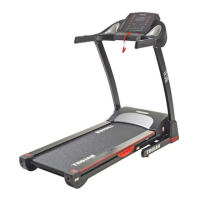
STEP 3:
STEP 3
Use the Screwdriver to remove the 4 S
crews (M5 x 12) (22) from the Left
upright (3) and Main Frame (2).
Install the Left base cover (44) to the Lef
t Upright (3) using the Screwdriver and 4
Screws (M5 x 12).
Use the Screwdriver to remove the
4 Screws (M5 x 12) (22) from the Right
Upright (4) and Main Frame (1).
Install the Right base cover (45) to
the Right upright (4) using the
Screwdriver and 4 Screws (M5 x 12).
#22M05T003 TR510 Treadmill - User Manual.indd 11 2022/05/25 14:49
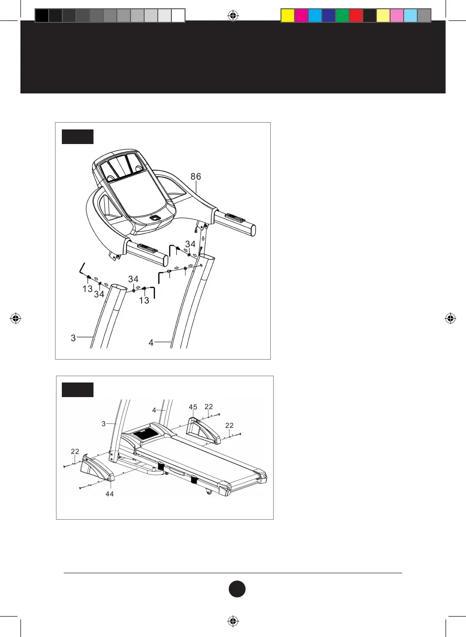
STEP 4
STEP 4:
Use the 5# Wrench to connect the
cable from the Console (86) with the cable
from the Right upright (4) and the Left
Upright (3) using 4 Bolts (M8 x 15) (13) and
4 Washers (M8) (34)
NOTE: Make sure that the cables are
connected correctly before tightening all
Bolts.