Truefitness.com / 800.426.6570 / 636.272.7100 13
CHAPTER 2: ASSEMBLY INSTRUCTIONS
TREADMILL ASSEMBLY STEPS (continued):
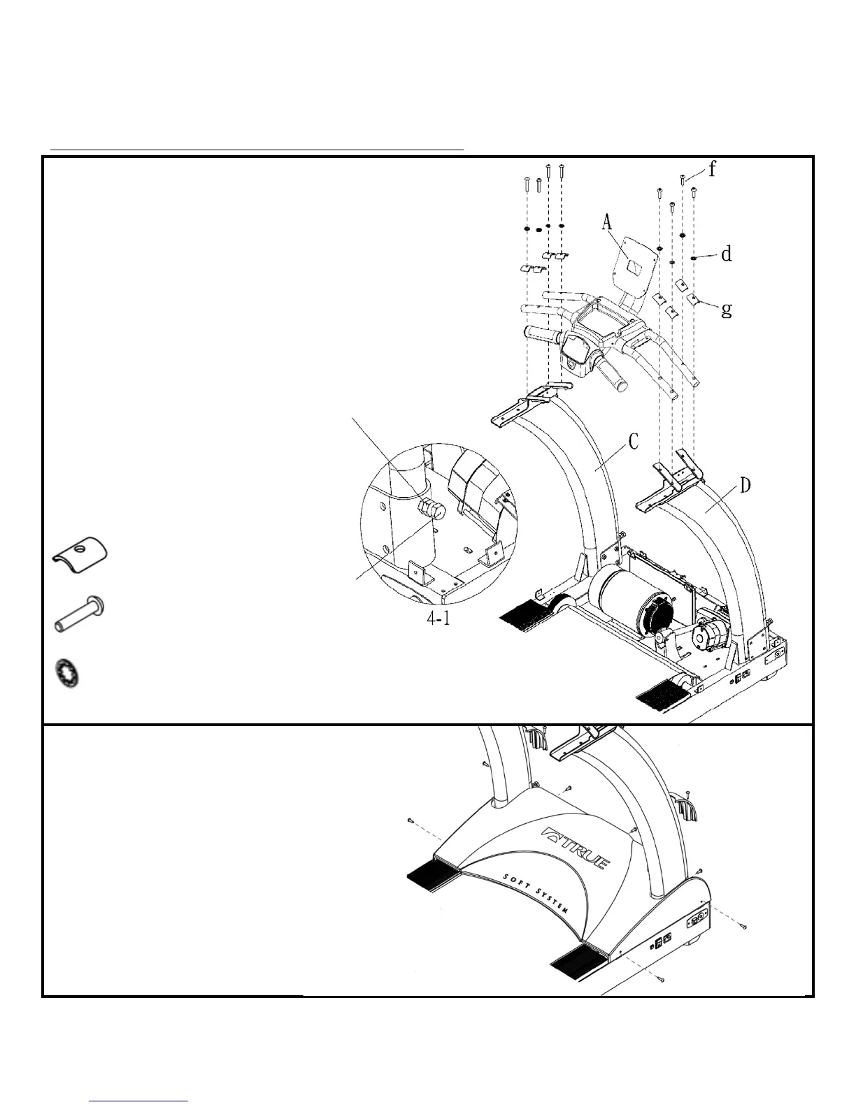
STEP 4: Console Rack and Motor Cover Installation:
a) Install Console Rack (A) onto
Pedestals R & L by resting Console
Rack tubing on top of Pedestal tubing
cradles.
b) Using 5 mm Hex Key, install but
d
o not tighten, 8 Shoulder Plates (g),
8 Bolts-M8 x 40mm (f) and 8 internal
tooth washers (d) through Console
Rack tubing and into Pedestal tubing
cradles. Once all eight bolts are
installed, tighten all bolts.
c)
T
ighten the 8 Bolts that secur
e
P
edestals to Frame. (see step 2)
d)
U
se a 17mm wrench to tighten two
Hex Head Bolts until secure against
Pedestal legs. Then tighten two nuts
to secure Hex Head Bolts. See Fig 4-1.
Required Hardware:
8
Shoulder Plates (g)
8 M
8 x 40mm Bolts (f)
8 Internal Tooth M8 Washers (d)
e) Place Motor Cover onto frame.
Using a Phillips Screwdriver, install
Motor Cover into Frame with seven
Motor Cover screws. Install Motor
Decoration Covers with two screws as
shown.
Required Hardware:
Hardware from step 1.