TR-36RBF INSTALL GUIDE
07/28/2021 Page 17 of 48TEC_TM_151 | REV. A | EN
WARNING – To avoid a hazard from
appliance instability, install the anti-
tip bracket in accordance with the
instructions below.
BEFORE YOU BEGIN
Consult a flooring expert to confirm that the flooring
where the unit will be installed is rated for at least 150
pounds per square foot.
1. Measure and mark the depth of the bracket’s
placement in the installation location.
• Flush installation: 24-31/32” (634 mm)
• Proud installation: 22-31/32” (584 mm)
2. Place and center the bracket at the measured
depth.
3. With the bracket as a guide, drill pilot holes into the
wall and/or floor.
NOTE: FOR INCREASED STABILITY, SECURE THE
BRACKET TO AS MANY JOISTS AND/OR STUDS AS
POSSIBLE.
4. With the provided hardware, secure the anti-tip
bracket.
5. Adjust the rear leveling rollers 1/4 turn clockwise.
6. Slide the unit into place and hook the anti-tip
bracket into the castor assembly slots.
INSTALLATION
ANTI-TIP BRACKET KIT:
• One (1) anti-tip bracket (Figure 1.1)
• Four (4) masonry 3/16” screws
• Eight (8) wood #12 – 2” screws
• Twelve (12) 1/4” washers
FOR ALL FULL SIZE RESIDENTIAL MODELS, THE ANTI-
TIP BRACKET ENGAGES WITH THE REAR LEVELING
LEGS TO SECURE THE UNIT. FOLLOW THESE STEPS
TO SECURE THE BRACKET BEFORE MOVING THE
UNIT INTO FINAL OPERATING POSITION.
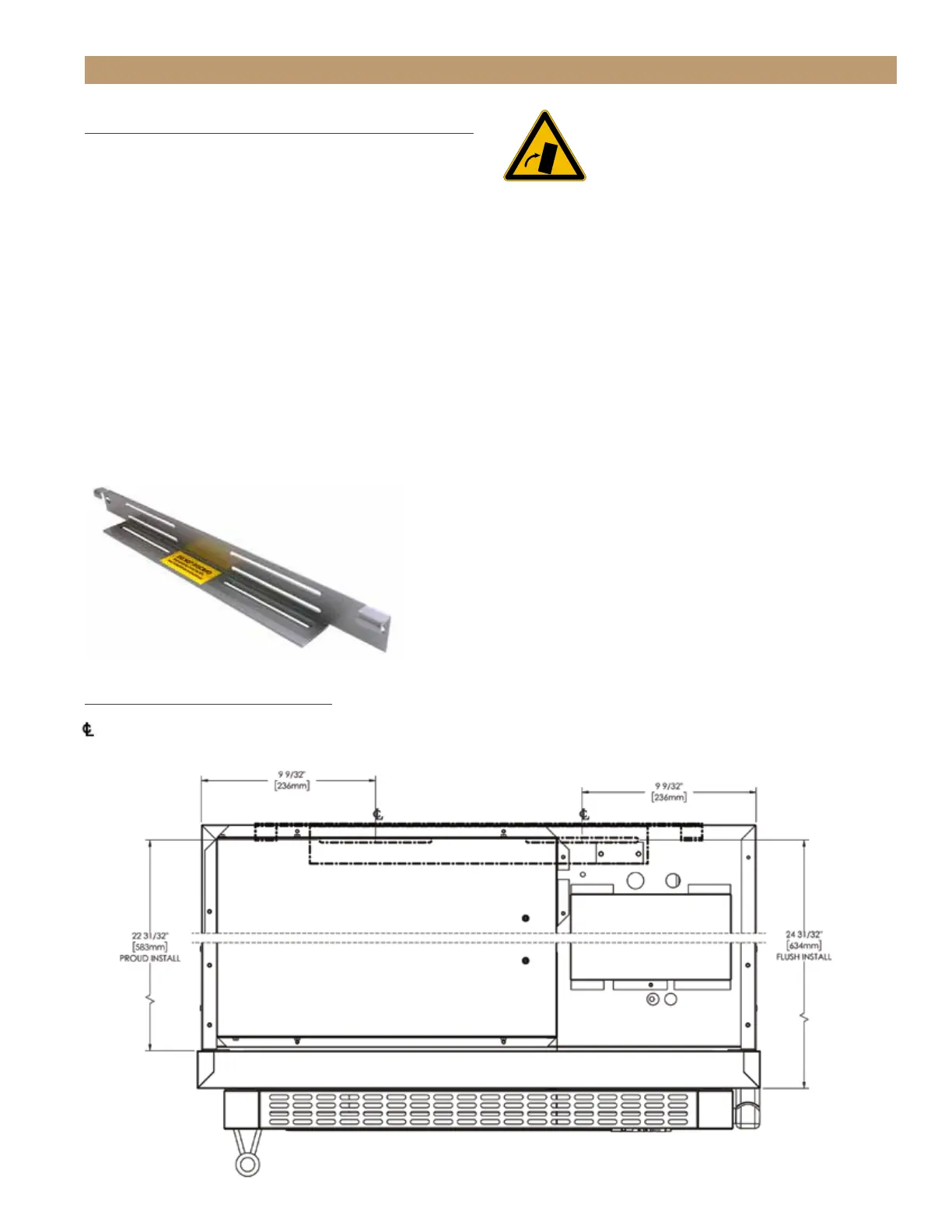
1. Determine final location of the unit. For a FLUSH
install, measure back 24-31/32” (Dimension A)
from the surrounding cabinetry. For a PROUD
install, measure back 22-31/32” (Dimension B)
from the surrounding cabinetry. For either type of
install, place the anti-tip bracket centered in the
rough opening.
2. Using the bracket as a guide, drill pilot holes into the
wall/floor. It is recommended to secure the bracket
to as many floor joists and wall studs as possible.
3. Using the provided screws and washers, secure the
bracket to the wall/floor. Adjust the rear rollers to
just above their lowest position and move the unit to
its final position. Raise the rear rollers a minimum
of 1/8” to engage the bracket.
FIGURE 1.1 - ANTI-TIP BRACKET
987036
5.19.17 AL
TRUE RESIDENTIAL REFRIGERATION
UPRIGHT ANTI-TIP BRACKET INSTALLATION
30 INCH UNIT
22 31/32"
583mm
PROUD INSTALL
24 31/32"
634mm
FLUSH INSTALL
9 9/32"
236mm
9 9/32"
236mm
C
L
C
L
NOTE: DIMENSIONS MAY VARY BY ±
1
/
8
”
WARNING: To avoid a hazard due to instability of
the appliance, it must be fixed in accordance with
the instructions.
AVERTISSEMENT: Pour éviter tout risque dú a
l´instabilité del l´appareil, vous devez le fixer
conformément aux instructions.
ANTI-TIP BRACKET INSTALLATION
KIT INCLUDES
• (1) One anti-tip bracket
• (4) Four 3⁄16” masonry screws
• (8) Eight #12-2” wood screws
• (12) Twelve 1/4” washers
TOOLS REQUIRED
• Tape measure
• Marking utensil
• 1/8” drill bit
• 7/16” socket
• Phillips bit driver
• Drill or ratchet
36RBF UNIT TOP VIEW
= Center Line
–-– = Bracket Location
NOTE: DIMENSIONS MAY VARY BY ± 1/8” (3.175 mm)
 Loading...