CHAPTER 2: ASSEMBLY GUIDE
Truetness.com / 800.426.6570 / 636.272.7100
36 of 62
TREADMILL ASSEMBLY STEPS:
Step 25 Exit Location (Optional):
Step 26 Treadmill Neutral Position (Optional):
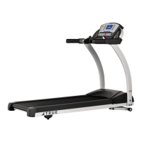
Conrm the cables are routed correctly through the two wire retainer clips to prevent cable pinching above the
incline rack wheels. Position the treadmill upright to restore it to the neutral position. Connect the male ends of
the Ethernet, coaxial, and power cables to the corresponding outlet(s). Restore the treadmill deck incline grade
to zero percent while conrming the three cables maintain correct positioning along the guide channel in the
cord management hardware.
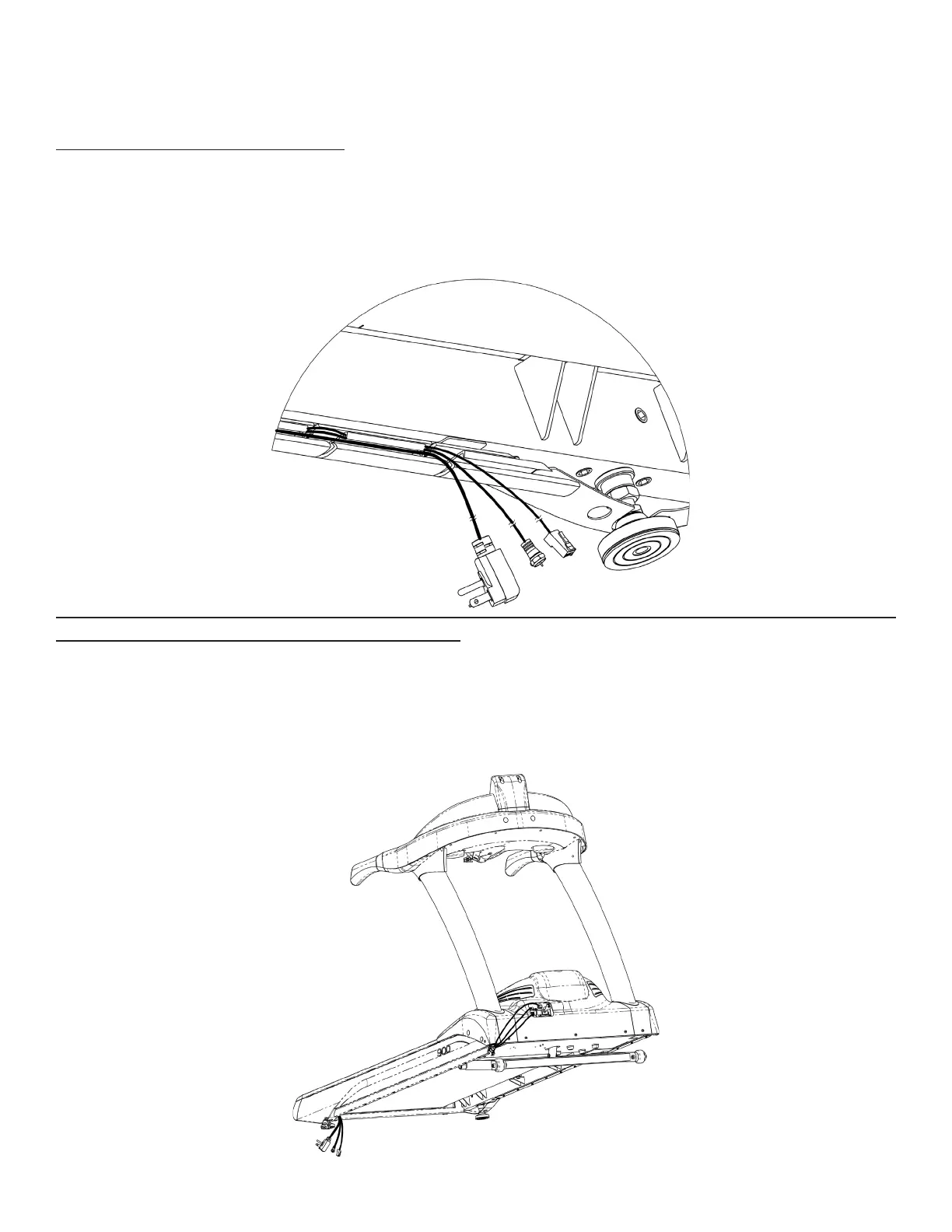
Shown below is the suggested exit location of the cables near the rear leveling foot, but the cables may exit at
other locations from the guide channel depending on the location of the corresponding outlet(s).
Note: To prevent cord entanglement with the running belt and rollers and reduce injury from tripping hazards,
the cords must not exit from or cross over the rear of the treadmill.