CHAPTER 2: ASSEMBLY GUIDE
Truetness.com / 800.426.6570 / 636.272.7100 15 of 62
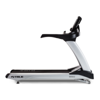
TREADMILL ASSEMBLY STEPS:
a) Secure the pedestals to the treadmill
frame using nine M8 x 25 bolts (a),
nine M8 lock washers (c), and one M8
locknut (d) where shown.
Note: Do not fully tighten the hardware
used in this step yet.
Note: Ensure the pedestal cables are
routed between the treadmill frame and
pedestal support brace as shown.
Hardware Required:
Qty. 9 M8 Lock Washers
Qty. 9 Bolts M8 x 25
Qty. 1 Lock Nut M8
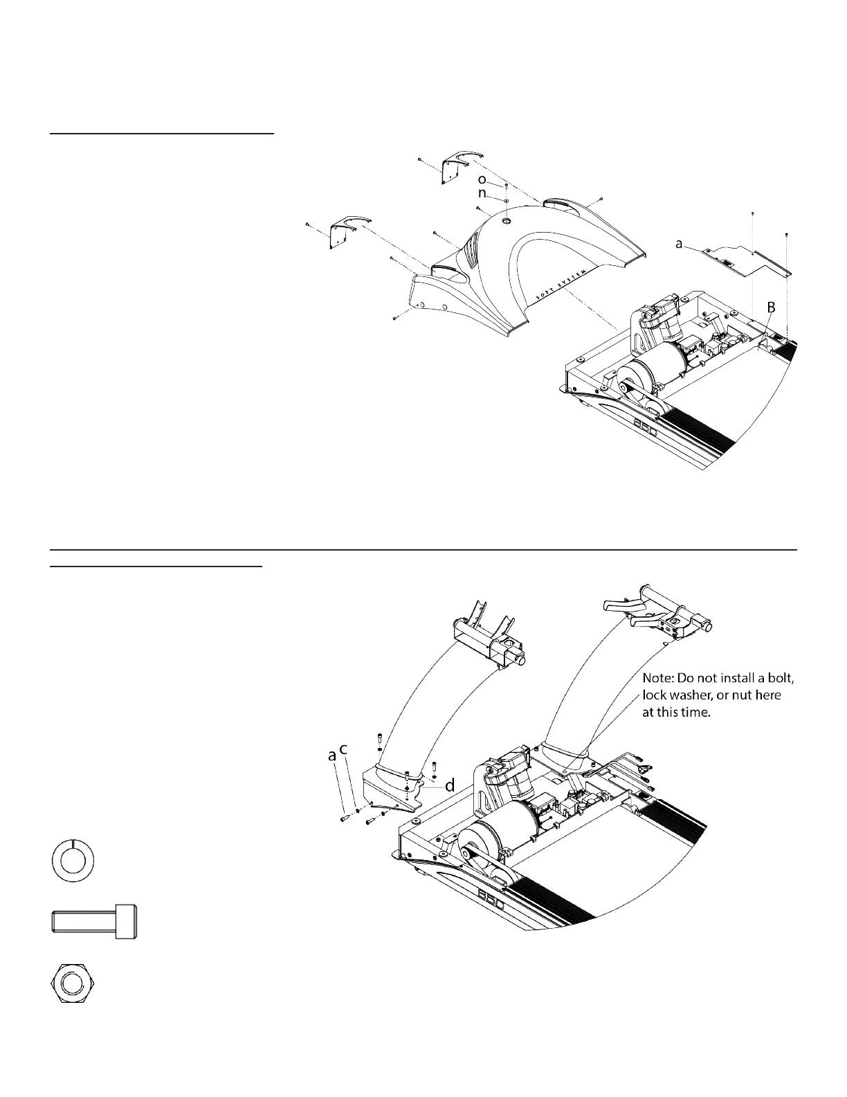
Step 1 Remove Motor Cover:
Step 2 Pedestal Installation:
a) Remove the screw (o) and washer
(n)and then the seven remaining
identied screws from the motor
cover. Keep all motor cover hardware
for reassembling the motor cover to
the treadmill frame at Step 11.
b) While pulling the sides slightly
outward, remove the motor cover
from the treadmill frame (B) by
pulling upwards. You will feel
some snap catches release while
performing this step.
c) Remove the Drip Guard Assembly
(a) from the treadmill frame. Keep
all drip guard assembly hardware for
reassembling the drip guard assembly
to the treadmill frame at Step 4.