10
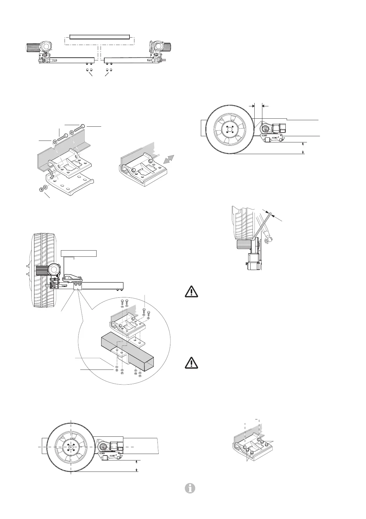
Loosely attach the drive units to the lateral bar. The bolts (lock
nuts) must be no more than finger-tight.
g
Fig. 21
Place the mounting set (b) on the vehicle frame and secure
using the two bolts (c), tight enough so that it can just about
be moved on the frame.
M8 x 60 (4 x)
Self-locking nut M8 (4 x)
Washer 8
(8 x)
Fig. 22
Bolt drive units with lateral bar to mounting set using U-brack-
et (d), tight enough so that it can just about be moved.
d
M10 x 50 (8 x)
Self-locking
nut M10 (8 x)
Washer 10
(16 x)
Fig. 23
Position the drive rollers so that they are approximately at the
height of the wheel hub / centre.
min. 110 mm
Fig. 24
Truma can supply a spacer plate set for compensating for
height differences of up to 45 mm (part no. 60010-66000,
2 pcs. à 15 mm). Up to three spacer plates can be used at
each side. A bolt set (part no. 60010-70000) is needed to
attach the spacer plates.
The low chassis mounting set (part. no. 60010-64900) must
be used for height differences of more than 45 mm. Check
that there is adequate ground clearance (min. 110 mm).
The correct distance can be set between the tyre and the
roller (20 mm) with the provided spacer by sliding the (disen-
gaged) drive units in the longitudinal direction. The movable
middle tube makes it possible to adapt to the width of the
frame.
20 mm
min. 110 mm
Fig. 25
Slide drive units in lateral direction so that the maximum
amount of tyre tread is covered.
Ensure that there is adequate clearance between the gearbox
and the tyre / shock absorber so that they do not touch.
min.
10 mm
Fig. 26
The minimum clearance with the drive units engaged is
10 mm.
After correctly positioning the bolts and nuts of the mounting
set, tighten slightly and then check the required distances /
clearances again. The weight of the caravan must be on the
wheels when doing this.
Place the movable connection pipe in the centre (use the
marking) and fix each side with 2 threaded bolts (g) M8 x 12
(15 Nm).
The threaded bolts are coated with sealant, and may
therefore only be bolted in once.
Re-check the distance of 20 mm to the tyre (with weight on
wheels) and then tighten the 2 mounting set bolts (M8) with
24 Nm and the 4 mounting set bolts (M10) with 48 Nm.
The bolt tightening order must be strictly adhered to for cor-
rect installation.
48 Nm
48 Nm
24 Nm
Fig. 27
Re-check that all 6 bolts have been tightened to the
correct torque!