7
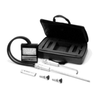
Static Pressure Probe
Step 1: Remove sensing port caps.
Step 2: Connect two hoses (C) to sensing ports (D).
Step 3: Select proper Range Selector (D).
Note: For 0–1" static pressures, use Range Selector with black letters;
for 1–10" static pressures, use Range Selector with red letters.
Step 4: Connect the hoses to the Range Selector (D) as follows:
For Positive Pressure Measurements
Connect the plus (+) sensing port of the meter to the plus (+) sensing
port of the Range Selector. Connect the minus (–) sensing port of
the meter to the minus (–) sensing port of the Range Selector.
For Negative Pressure Measurements
Connect the plus (+) sensing port of the meter to the (–) sensing port
of the Range Selector. Connect the minus (–) sensing port of the
meter to the plus (+) sensing port of the Range Selector.
Step 5: Select the proper Static Pressure Probe (E)
Note: For 0–1" static pressures, use the Static Pressure Probe with
black letters. For 1–10" static pressures, use the Static Pressure Probe
with red letters.
Step 6: Insert the Static Pressure Probe (E) into the Range Selector
(D). Push the probe firmly down until the collar of the probe rests against
the top of the Range Selector.
Step 7: Check position of switch button (Da) on the Range Selector (D).
It must be pushed in and turned to lock it in position.
Step 8: Check position of switch plate (Db) on the Range Selector (D).
It must be to the extreme left.
Step 9: Proceed to make duct static pressure measurements. See page
13 for proper procedure.
 Loading...