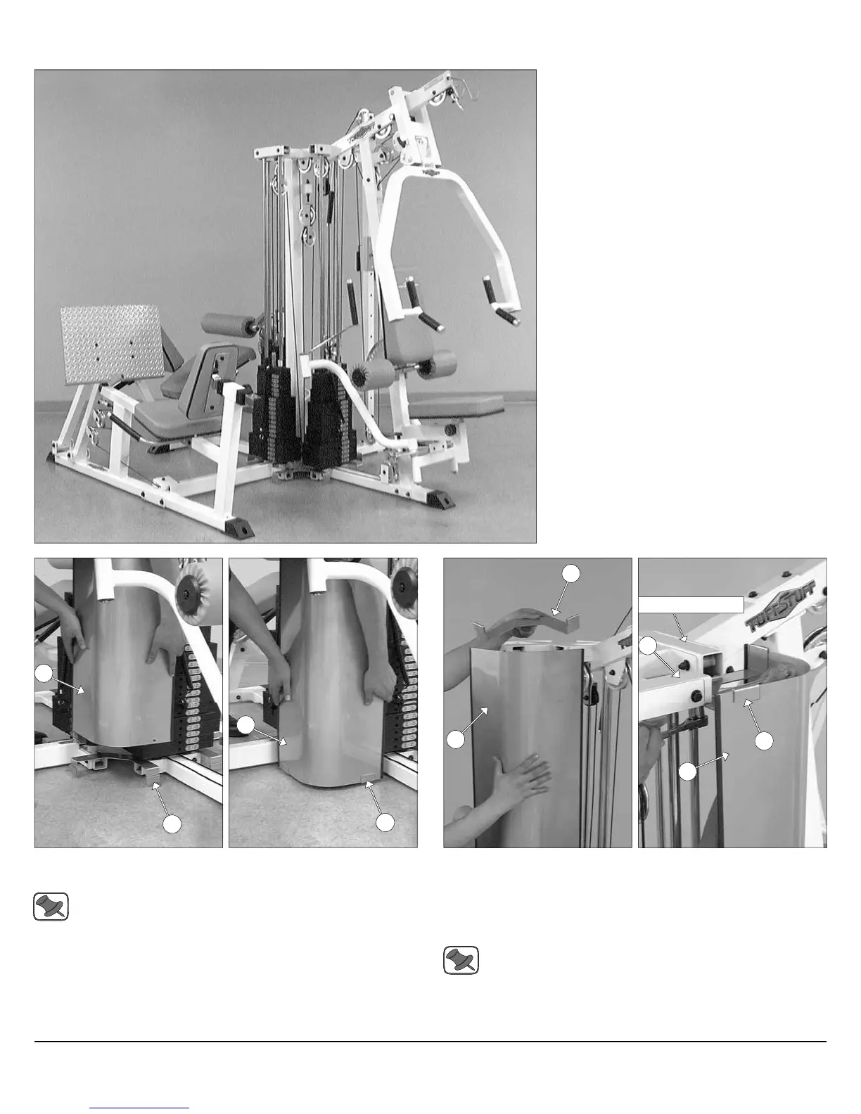
FIG. 68 Insert one of the Weight Shields (#50) to one of the bottom
Weight Shield Holder (#52) as shown above
Note: Refer to the illustrations shown on fold-out page 28 for fur-
ther clarification of this hardware assembly.
FIG. 67 Before assembling the Weight Shields
(#50 & #51), inspect and adjust the cables to ensure
a safe and smooth operation.
FIG. 69 Next, insert one Weight Shield Holder (#52) to the top of the
Weight Shield (#50). Next, secure the Weight Shield Holder (#52)
along with the Weight Shield (#50) to the two adjacent Guide Rod Re-
tainers (#17) using two Hex Head Cap Screws 3/8-16 X 3/4 (#102), and
two Nylon Insert Lock Nuts 3/8-16 (#119).
Repeat the same process for the three other Weight Shields (#50).
Note: Refer to the illustrations shown on fold-out page 28 for fur-
ther clarification of this hardware assembly.
50
52
52
50
52
50
52
50
Guide Rod Retainer
17
28
Assembly Instructions
Apollo Modular Gym System (Base Unit)