Installing
Mounting the sensor on ferrous shafts (Ø ≤ 14mm) or non-ferrous shafts
Hans Turck GmbH & Co. KG | T +49 208 4952-0 | more@turck.com | www.turck.com
V01.00 | 2023/06 | 10
5 Installing
The device can be mounted without mounting accessories on rotating shafts made from fer-
rous material with diameters of up to 14mm or on non-ferrous shafts. For ferrous shafts with
larger diameters, mounting kit BTS-DSU35-Z02 is required:
NOTICE
Insufficient clearance from metal surrounding the positioning element
Loss of function due to weakening of the oscillating circuit!
Ensure sufficient clearance between the surrounding area and positioning ele-
ment.
Carry out a function test prior to commissioning.
n Avoid static charges on plastic devices and cables.
n Do not mount the device in a dust flow and avoid build-up of dust deposits.
n Protect devices and cables against mechanical damage.
n To avoid contamination, remove the housing covers and plug only shortly before mounting.
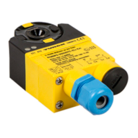
5.1 Mounting the sensor on ferrous shafts (Ø ≤ 14mm) or non-ferrous shafts
Fig.2: Mounting the sensor — shaft diameter of up to 14mm
The positioning element must be centered within the sensor's detection range. The following
prerequisites must be fulfilled for this purpose:
n The shaft protrudes 19.75mm from the mounting surface.
n The shaft features a groove as anti-rotation protection for the positioning element.
Screw the sensor on to the mounting surface.
Fit the positioning element on the shaft.
Align the positioning element in the center of the sensor's detection range. The ideal dis-
tance to the upper and lower sensor edge is 0.65mm.
Attach the positioning element. The nominal distance between the sensor and position-
ing element is 1mm.

 Loading...