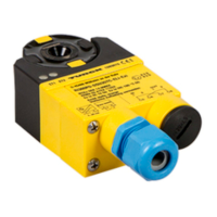
Connection
Hans Turck GmbH & Co. KG | T +49 208 4952-0 | more@turck.com | www.turck.com
V01.00 | 2023/06 | 12
6 Connection
5 IN1
6 IN2
7 OUT1
8 OUT2
2
3
1
4 Easyteach
–
+
I
Fig.4: Wiring diagram
Fig.5: Removing the housing part
Open the terminal chamber via the external cable glands and remove the housing part.
Insert stranded wires with a stripped length of 6mm and suitable wire end sleeves into
the terminal chamber.
Connect the connection cable to the connector strip according to the wiring diagram.
Close the housing and secure the screws.
Connect the open end of the connection cable to the power source and/or evaluation
devices in accordance with the wiring diagram.

 Loading...