21
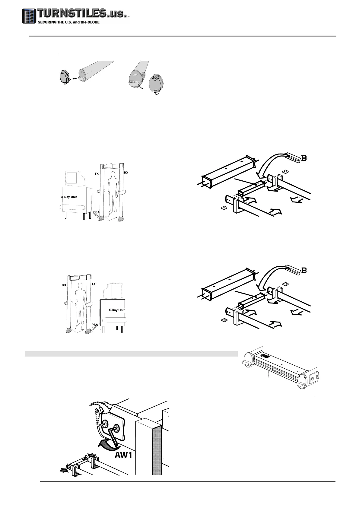
Attaching the crossbar
Remove the protection caps c of the columns, to access the inner connectors.
c
c
ATTENTION! According to the suitable configuration, the crossbar must be oriented so that the
archway assembly can be performed in the easiest way.
Configuration A (with TX column on the left when facing the exit side).
Place the crossbar as illustrated in the figure below (holes for the control unit close to the TX
column).Insert the crossbar guide pins into the holes on the inside of the column.
Configuration A
TX
RX
Configuration B (with TX column on the right when facing the exit side).
Place the crossbar as illustrated in the figure below (holes for the control unit close to the RX
column). Insert the crossbar guide pins into the holes on the inside of the column.
Configuration B
TX
RX
Note: Mount the crossbar with the groove cc at the top.
Secure the crossbar with the knobs vt, using the AW1 Allen key
(Tightening torque: 10 Nm).
vt
C1
cc
303-670-1099
 Loading...