5
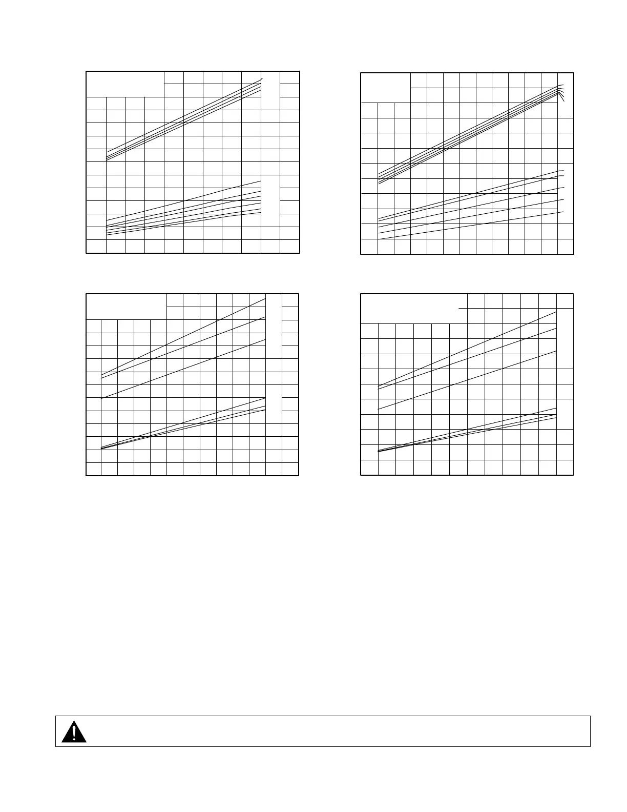
PERFORMANCE CURVES
OPERATING THE BLOWER
1. Inspect blower mounting, drive line, PTO, and air lter for integrity.
2. Remove Camlock dust cap and connect the hot air hose.
3. Follow trailer instructions regarding product hose connection and valve operation.
4. Slowly engage PTO with engine at idle, and blower unloaded. Bring up to operating speed and lock engine at recommended
speed (Shown in cab)
5. Unload trailer as per trailer manufacturer’s recommendation and do not exceed maximum tank pressure or maximum blower
pressure.
6. While discharging, visually check blower for vibration, mechanical noise or excessive heat.
7. If relief valve is opening, adjust proportioning valve to reduce tank pressure.
8. Reduce pressure to zero as per trailer manufacturer’s instructions.
9. Disengage PTO
10. Disconnect blower hose and replace Camlock dust cap.
WARNING: The blower and accessories become hot and will cause serious skin burns on contact. Rotating
machinery is dangerous. Always wear ear protection when in close proximity to the blower.
BHP
AIRFLOW BASED UPON
INLET CONDITIONS OF:
14.7 PSIA & 70° F
0
10
20
30
40
50
60
600
550
500
450
400
350
300
250
1000 1250 1500 1750 2000 2250
PSIG
25
20
18
15
12
10
PSIG
10
15
20
25
CFM
Airflow at Inlet (CFM)
Horsepower (BHP)
1000 1200 1400 1600 1800 2000 2200
10
14
17
17
14
10
0
5
10
15
20
25
30
200
250
300
350
400
450
500
550
600
RPM
BHP
AIRFLOW BASED UPON
INLET: 70° F
DISCHARGE: 29.92” Hg Abs.
"Hg
"Hg
CFM
T650 VACUUM CURVE
Airflow at Inlet (CFM)
Horsepower (BHP)
AIR FLOW AT
STANDARD INLET
CONDITIONS
1013mb + 20°C
kW
0
10
20
30
40
50
60
0.5
1
1.5
2
2.2
bar
0.5
1
1.5
2
2.2
bar
400
500
600
700
800
900
1000
1100
m³/h
1200 1400 1600 1800 2000 22001000
RPM
Airflow at Inlet (m³/h)Kilowatts (kw)
350
475
575
575
475
350
AIRFLOW BASED UPON
INLET: 20°C
DISCHARGE: 1 BARA
DENSITY @ 20°C & 1 BARA: 1.2 KG/M³
kW
0
5
10
15
20
25400
300
500
600
700
800
900
1000
1100
m³/h
1200 1400 1600 1800 2000 22001000
mbar
mbar
RPM
Airflow at Inlet (m³/h)Kilowatts (kw)