7
CHECK VALVE
• Minimum restriction for application and mounted downstream of the relief valve.
• The check valve should be sized for maximum air flow (CFM).
SUCTION & DISCHARGE PIPING
• All piping should be free and clear of any welding slag or foreign material.
• The suction piping requirements is a minimum of 4’’ (100 mm) diameter for proper flow to the blower.
• The discharge piping is recommended to be 3” (80 mm) diameter.
CAUTION: Do not use a rubber elbow in the suction line during vacuum operation. The elbow will fail causing the
blower to overheat. This will cause damage to the blower.
MUFFLERS & DISCHARGE FILTRATION
• Minimum restriction for application
• Mount downstream of relief valve.
CAUTION: For food-grade applications, always install a properly sized food-grade discharge filter downstream of
the muffler (between muffler and trailer).
VACUUM VALVE
• A vacuum valve and filter must be installed to properly protect
the blower from overheating while vacuum loading.
• Size for proper air flow and vacuum rating.
• This valve should be located before the blower inlet air filter.
Normally this valve is mounted on the trailer.
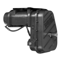
PTO DRIVE SHAFT
• Blower drive shaft and PTO output shaft must be parallel and
in phase. Maintain axis within one degree in vertical plane to
ensure low vibration during operating conditions.
• Use a minimum of a 1300 series (SAE 1300 or DIN 100) drive
shaft that has been correctly balanced at the operating RPM.
• Do not force yokes onto the blower drive shaft or the PTO
output shaft.
• T650 drive shaft is 1 5/8” diameter with a 3/8” keyway and
2-9/16” inches long.
• T950H drive shaft is 40 mm diameter with a 12 mm keyway
and 65 mm long.
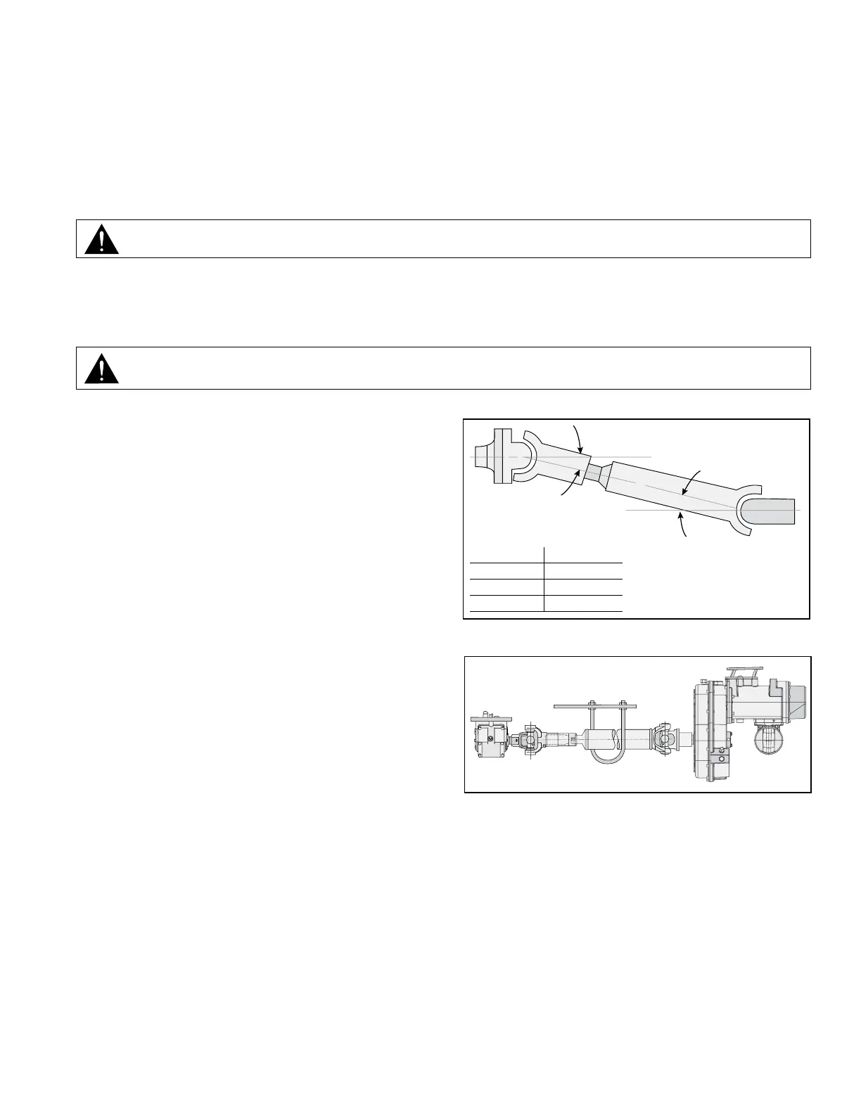
• Refer to Figure 2 to ensure that the drive shaft is at the
proper angle.
• A “U” bolt hanger (Figure 3) should be installed to prevent the
drive shaft from damaging the blower or PTO if the slip yoke
comes apart. The slip joint should be half compressed. This
will also stop the drive shaft from dropping to the ground, and
causing potential thrust damage to the blower.
DRIVE SHAFT ANGLE
(Horizontal Plane)
SPEED ANGLE
1250 RPM 12 Degrees
1650 RPM 10 Degrees
2000 RPM 8 Degrees
THE ANGLE OF THE
DRIVE SHAFT SHOULD
NOT EXCEED 12°
Figure 2. Drive Shaft Angle
Figure 3. U Bolt Hanger Installation