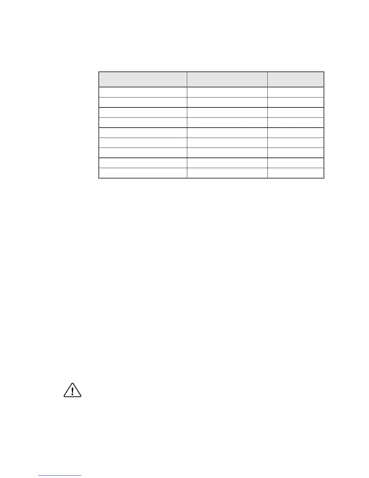
Circuit Breaker
2540
1Ph, 230V/50/60Hz 20A
3150/70
1 or 2 Ph, 230V/50/60Hz 25A
3850/70
3 Ph, 208V/50/60Hz 25A
3850/70
3 Ph, 230V/50/60Hz 25A
3850/70 with switching box
1 or 2 Ph, 230V/50/60Hz 30A
3850/70, 5050/75
3 Ph, 400V/50/60Hz 20A
5050/75
3 Ph, 208V/50/60Hz 30A
5050/75
3 Ph, 230V/50/60Hz 30A
5050/75 with switching box
1 or 2 Ph, 230V/50/60Hz 45A
If the autoclave is a 3 phase 3870, 5050 or 5075 autoclave and has to be connected
to a one phase power network, 1 x 230V, 50/60Hz., connected the 1ph 230V
power source to the supplied switch box that has a 1 phase input (from the power
source) and a 3 phase output (to the autoclave). See details at the end of this
manual.
The power network must be protected by a current leakage relay.
Mineral-free water having a conductibility lower than 15µs (microsiemens),
through a 1/2” flexible hose.
To obtain water quality meeting requirements a deionization column or reverse
osmosis apparatus can be installed. The water must be delivered at a pressure of 2-
3bar. A pressure reducer shall be installed at the water source outlet as instructed
below.
For fast cooling (if this option is provided):
Feed water from the water network, pressure 2-3bars, connected through a 1/2”
pipe. A pressure reducer shall be installed at the water source outlet as instructed
below.
Compressed air, from a mobile compressor or compressed air network at pressure
3-4 bars, will be set at 1.6-2bars at the autoclave inlet is to be connected by a
flexible conduit of 3/16”.
The air must be of instrumental quality filtered at 5µ and free of humidity and oil
drops.
Drain connected by 1/2” pipe, located at the rear of the unit. The chamber exhaust
and coolant water is evacuated to an open waste funnel. The drainage piping must
be heat resistant, to 80ºC, non-continuous flow.
Attention:
Connection of water system to the autoclave must be performed through "BACK
FLOW PREVENTION SYSTEM" installation as per EN 1717:2001 regulations
and local regulations.
.



 To Next Page