Operation
OperationOperation
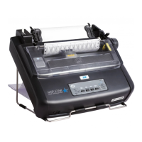
Operation
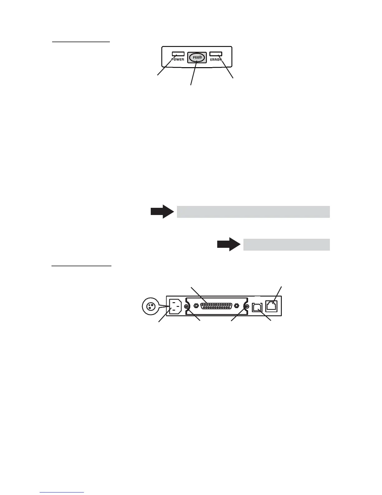
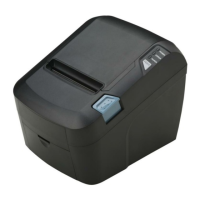
Panel
PanelPanel
Panel
POWER LED
ERROR LED
FEED button
● POWER LED
Illuminated when the printer power is on and off when the printer power is
off. May blink or light in a special mode or in case of failure.
● ERROR LED
Illuminated or blinks when paper is empty or in case of failure.
The interval length of blinking represents the type of error.
● FEED button
Pressing this button once causes the paper to feed one line. The longer the
button is pressed, the more paper is fed.
Pressing this button causes the paper to feed to the next Black Mark position
in Black Mark mode.
See 5.3 Manual Setting of Memory Switch
In case of auto cutter error, press the FEED button after removing the cause
of the error.
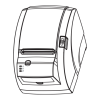
Rear Connectors
Rear ConnectorsRear Connectors
Rear Connectors
Power connector
(DC power supply type)
Interface connector
(Serial, parallel, etc.)
See 4.6 Error Indication
Cash drawer
kick-out connector
AC inlet
Interface board
USB connector
(AC power type) mounting screws
● Interface connector (Serial, parallel, etc.)
Connects to the interface cable. A DIP switch is provided on the serial interface
board.
● Cash drawer kick-out connector
Connects to the cable from the cash drawer.
● AC inlet (AC power type)
Connects to the AC power cord.
● Power connector (DC power supply type)
Connects to the cable from DC power source.
— 13 —