XPLR-AOA-3 - User guide
UBX-22006906 - R07 ANT-B10 Page 13 of 46
C1-Public
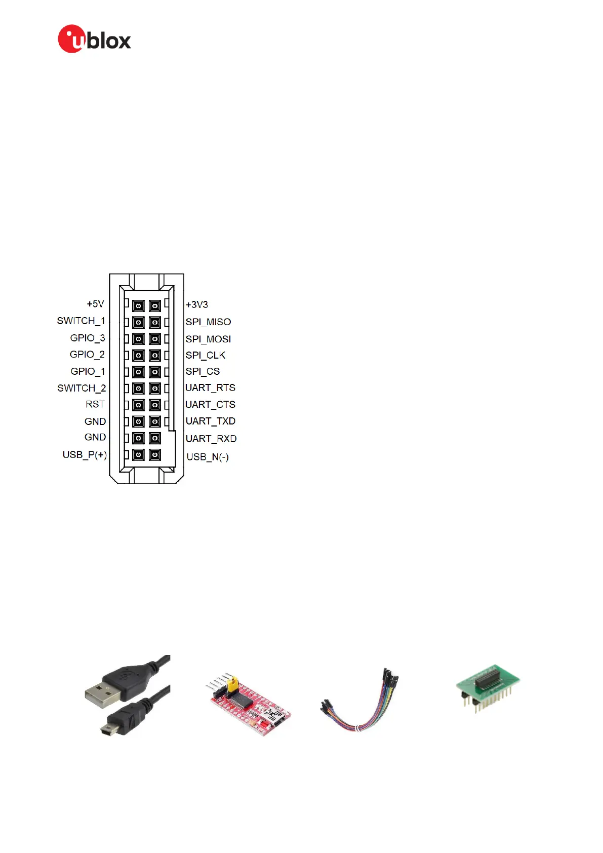
3.4.2 Pin description for UART connection
Using the cable harness, connect the following pins from the ANT-B10 header to USB-to-Serial
adapter:
• UART_TXD (pin 16)
• UART_RXD (pin 18)
• UART_CTS (pin 14) – optional for UART flow control
• UART_RTS (pin 12) – optional for UART flow control
• GND (pin 15 or 17)
• +3V3 (pin 2)
☞ If flow control is not used the UART_CTS pin is internally pulled down, but it is good practice to
connect UART_CTS to GND.
Figure 10 shows the pin positions on the ANT-B10 connector.
Figure 10: ANT-B10 connector pin assignment (top view)
3.4.3 Suggested accessories
Figure 11 shows (from left to right) the components needed to connect ANT-B10 directly to the
host PC.
• USB adapter cable with male USB Type-A connector to male mini-B connector
• FTDI FT232RL USB-to-TTL Serial Converter Adapter Module 5 V and 3.3 V for Arduino
• Female-to-female jumper set
• Dual-row, 1.27 mm pitch, 20-pin, female adapter (to avoid pin damage on the ANT-B10 board)
 Loading...