XPLR-AOA-3 - User guide
UBX-22006906 - R07 ANT-B10 Page 12 of 46
C1-Public
☞ By default, the “Print UUDF events on console” check box is deselected. This means that +UUDF
angle events are not printed on the console.
3.4 Connecting to a PC
3.4.1 Overview
A host PC can communicate directly with ANT-B10 over UART interface (TX, RX, CTS, RTS) through
EVB-ANT-1. The pin-headers connecting the two boards together is physically located in the center
of each board. See also Assembling the kit.
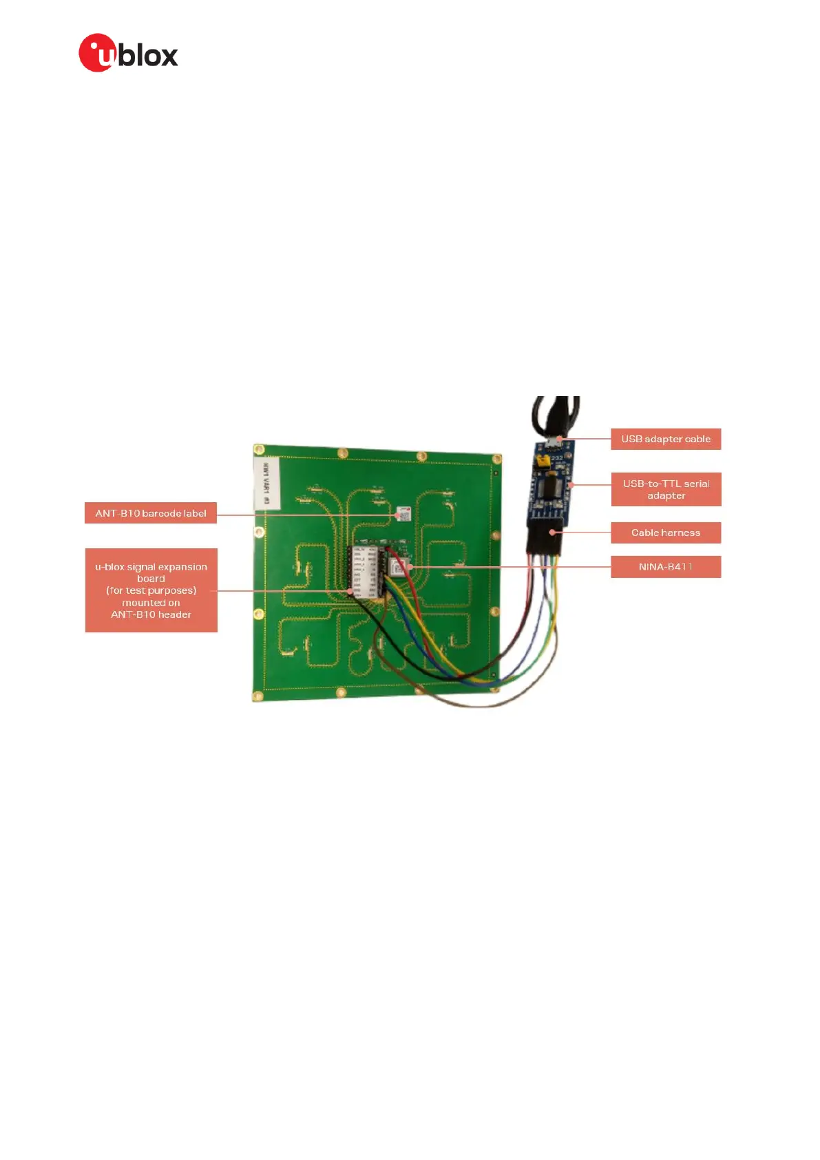
To test ANT-B10 as a standalone unit independently of EVB-ANT-1, the host PC can also attach to
the UART interface through an expansion board fitted to the underside of the antenna board.
Attaching a USB-to-TTL serial adapter to the expansion board with an adjoining cable harness allows
convenient access and control of the UART interface from the PC through the ANT-B10 header.
Figure 9 shows the USB adapter attached to ANT-B10 through the standard 1.27 mm pin header.
Figure 9: ANT-B10 with UART to USB serial converter
☞ As ANT-B10 is powered by the USB-to-Serial Adapter there is no need for external power
supply.
To connect ANT-B10 to the host PC:
1. Plug in the USB-to-Serial adapter
2. Open the Windows Device Manager to identify the COM port number of the board.
3. Use s-center [7] or your preferred terminal emulator to establish the serial connection to the COM
port.
4. Connect the COM port to the s-center tool [7] or the terminal emulator with the following port
settings:
• 115200 kbps
• 8 data bits, no parity, 1 stop bit (8N1)
• Flow control enabled using RTS/CTS
 Loading...