XPLR-AOA-3 - User guide
UBX-22006906 - R07 Product description Page 7 of 46
C1-Public
2.2 Assembling the kit
1. Connect to the ANT-B10 board to the EVB-ANT-1 board. Physically align the boards and gently
plug the 20-pin, male and female, header connectors together. Figure 2 shows the location of the
header connectors on each board.
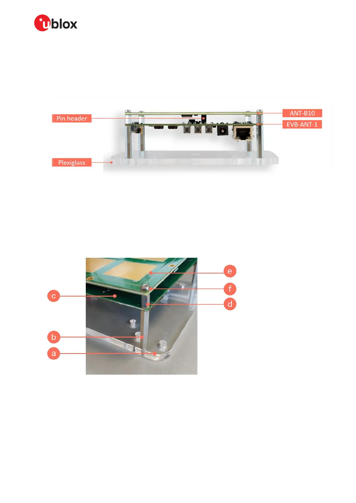
Figure 2: Assembled XPLR-AOA-3 kit showing EVB-ANT-1 and ANT-1 headers
2. Using the supplied standoffs and screws, assemble the two PCBs to the plexiglass, as shown in
Figure 3. The assembly order of the components (see Kit includes) are as follows:
a. Plexiglass
b. M3 30 mm standoff
c. EVB-ANT-1 PCB (connector side up)
d. M3 8mm standoff
e. ANT-B10 PCB with connector side down, fix the connectors together
f. M3x6 screw
Figure 3: ANT-B10 and EVB-ANT-1 with plexiglass enclosure
☞ The plexiglass has a 3/8” UNC thread available in the middle of the panel. This can be used to
connect tripods or via an adapter set use ¼” camera clamps or tripods. It can also be used to
mount the anchor node to a wall or ceiling.
⚠ The EVB-ANT-1 PCB is electrostatically sensitive and should not be handled without proper
precautions.
 Loading...