ZED-F9T-Integration Manual
3.2.2 Interface
Geofencing can be configured using the CFG-GEOFENCE-* configuration group. The geofence
evaluation is active whenever there is at least one geofence configured.
The current state of each geofence plus the combined state is output in UBX-NAV-GEOFENCE with
every navigation epoch.
Additionally the user can configure the receiver to output the combined geofence state on a physical
pin (assigned to a PIO being used for geofence state indication).
3.2.3 Geofence state evaluation
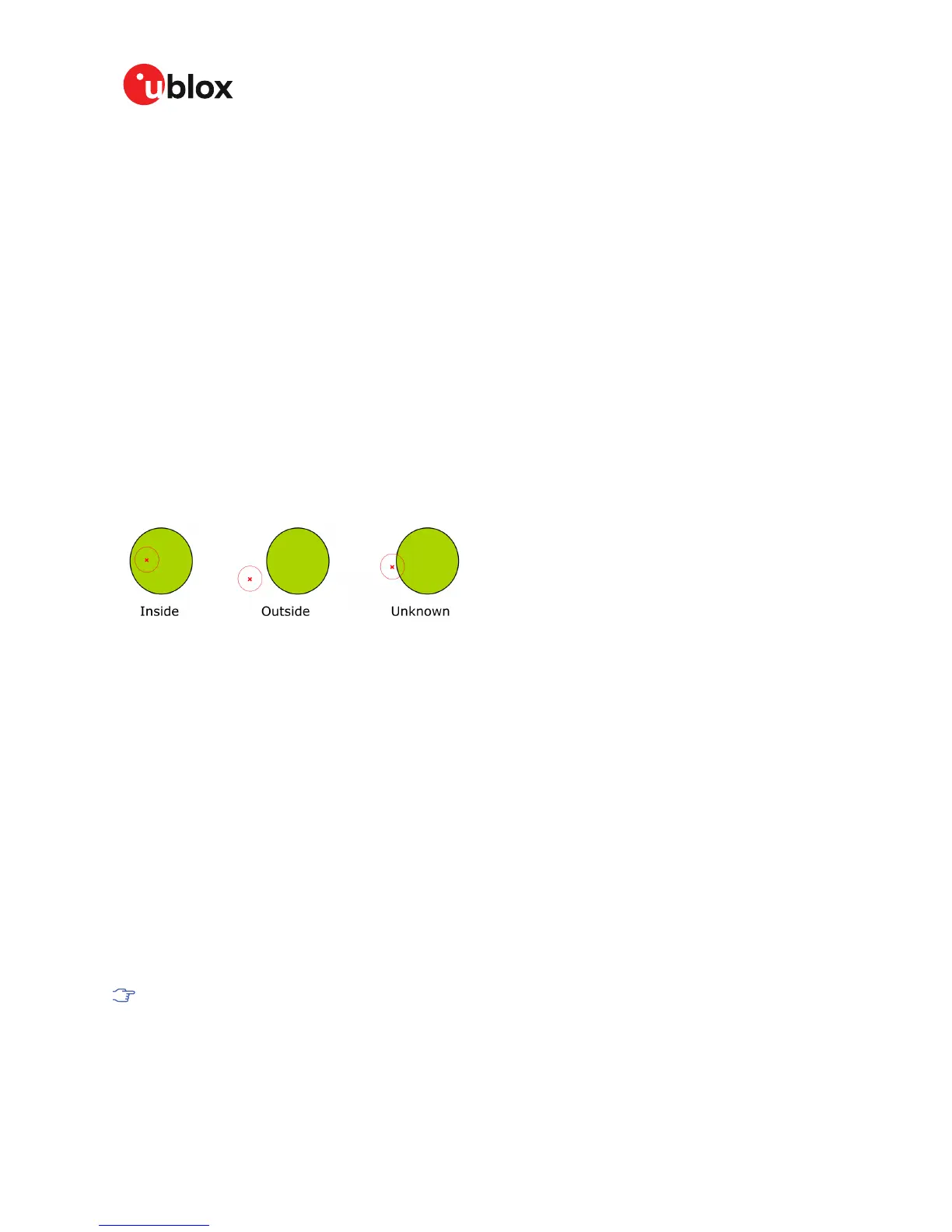
With every navigation epoch the receiver will evaluate the current solution's position versus the
configured geofences. There are three possible outcomes for each geofence:
•
Inside - The position is inside the geofence with the configured confidence level
•
Outside - The position lies outside of the geofence with the configured confidence level
•
Unknown - There is no valid position solution or the position uncertainty does not allow for
unambiguous state evaluation
The position solution uncertainty (standard deviation) is multiplied with the configured confidence
sigma level number and taken into account when evaluating the geofence state (red circle in figure
below).
Figure 6: Geofence states
The combined state for all geofences is evaluated as the combination (logical OR) of all geofences:
•
Inside - The position lies inside of at least one geofence
•
Outside - The position lies outside of all geofences
•
Unknown - All remaining states
3.2.4 Using the geofence pin state output
This feature can be used for example for waking up a sleeping host when a defined geofence
condition is reached. The receiver will toggle the assigned pin according to the combined geofence
state. Due to hardware restrictions, the unknown state will always be represented as HIGH. If the
receiver is in software backup or in a reset, the pin will go to HIGH accordingly. The meaning of the
LOW state can be configured using the CFG-GEOFENCE-PINPOL configuration item.
3.3 Interfaces
ZED-F9T provides UART1, SPI, DDC (I
2
C compatible) and USB interfaces for communication with
a host CPU. The interfaces are configured via the configuration interface which is described in the
ZED-F9T Interface Description [2].
It is important to isolate interface pins when VCC is removed. They can be allowed to float or
connected to a high impedance.
Some example isolation circuits are shown below.
UBX-19005590 - R01
3 Receiver functionality Page 21 of 80
Advance Information

 Loading...


