ZED-F9T-Integration Manual
4.7.3.3 VCC pads
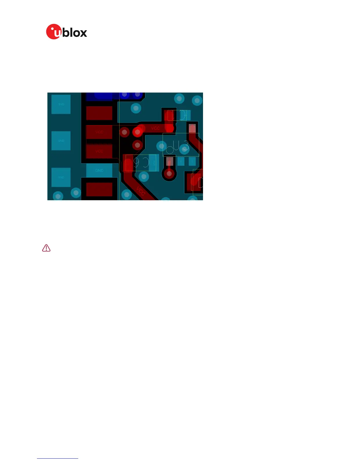
The VCC pads for the ZED-F9T high accuracy timing receiver need to be as low an impedance as
possible with large vias to the lower power layer of the PCB. The VCC pads need a large combined
pad and the de-coupling capacitors must be placed as close as possible. This is shown in the figure
below.
Figure 40: VCC pads
4.8 Design guidance
4.8.1 General considerations
Do not load Pin 4 (ANT_DETECT) with a capacitance more than 1 nF.
Check power supply requirements and schematic:
• Is the power supply voltage within the specified range?
• If USB is not used, connect the V_USB pin to ground.
• If USB is used, is there a 1 µF and a 100 nF capacitor right near the V_USB pin? This is just for
the V_USB pin.
• Is there a 1 µF cap right next to the module VCC pin?
• Compare the peak current consumption of the ZED-F9T GNSS module with the specification of
your power supply.
• GNSS receivers require a stable power supply. Avoid series resistance (less than 0.2 Ω) in your
power supply line (the line to VCC) to minimize the voltage ripple on VCC.
• Allow all I/O to Float/High impedance when VCC is not applied. See "Interfaces" section.
4.8.2 backup battery
Check backup supply requirements and schematic:
• For achieving a minimal Time To First Fix (TTFF) after a power down (warm starts, hot starts),
make sure to connect a backup battery to V_BCKP.
• Verify your battery backup supply can provide the battery backup current specified in the ZED-
F9T datasheet.
• Allow all I/O including UART and other interfaces to Float/High impedance in HW backup mode
(Battery Back-up connected with VCC removed).
UBX-19005590 - R01
4 Design Page 69 of 80
Advance Information

 Loading...


