ZED-F9T-Integration Manual
antenna if the supply voltage of the ZED-F9T module matches the antenna working voltage (e.g.
3.0 V).
A series current limiting resistor is required to prevent short circuits destroying the bias-t
inductor.
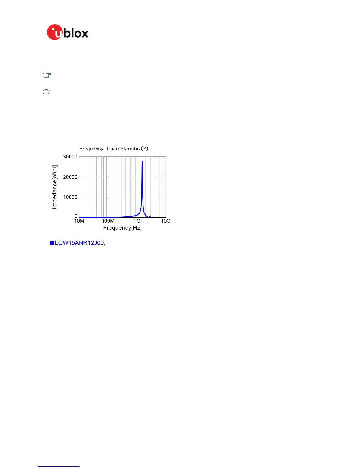
The bias-t inductor must be chosen for multi-band operation, a value of 120 nH 5% is
recommended for the recommended Murata L part. It has a self-resonance frequency of 1
GHz and a high impedance (> 500 Ω) at L-band frequencies.
The recommended bias-t inductor (Murata LQW15ANR12J00) has a maximum current capacity of
110 mA. Hence the current is limited to 70 mA at 3.3V using an active limiter in the recommended
circuit shown in Figure 33 below. A 10 Ω resistor (R2) is provided to measure the current. This resistor
power rating must be chosen to ensure reliability in the chosen circuit design.
Figure 32: ZED-F9T antenna bias inductor impedance
A recommended circuit design for an active antenna bias is shown below. This example shows an
external voltage of 3.3V with current limiting as described above. An ESD protection diode should
also be connected to the input as shown.
UBX-19005590 - R01
4 Design Page 62 of 80
Advance Information

 Loading...


