9
NOTE
Keep in mind that the door of the unit may be mounted on
either side of the cabinet (see REVERSING THE DOOR)
except for the 75 BEV. All U-Line units have a zero clear-
ance for the door to open when the hinge is on the right,
except for Stainless Steel Doors.
Additional clearance is needed for the Combo Models 29A,
29FF, and 75A only when the door hinge is on the left. See
built-in installation for additional clearance requirements for
these models.
Allow extra clearance, on hinge side, for a 90° door opening
when installed against a wall on all Stainless Steel
models.
U-Line recommends you consider additional clearance in front of the
open door for convenience.
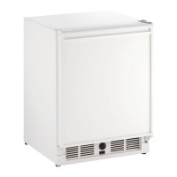
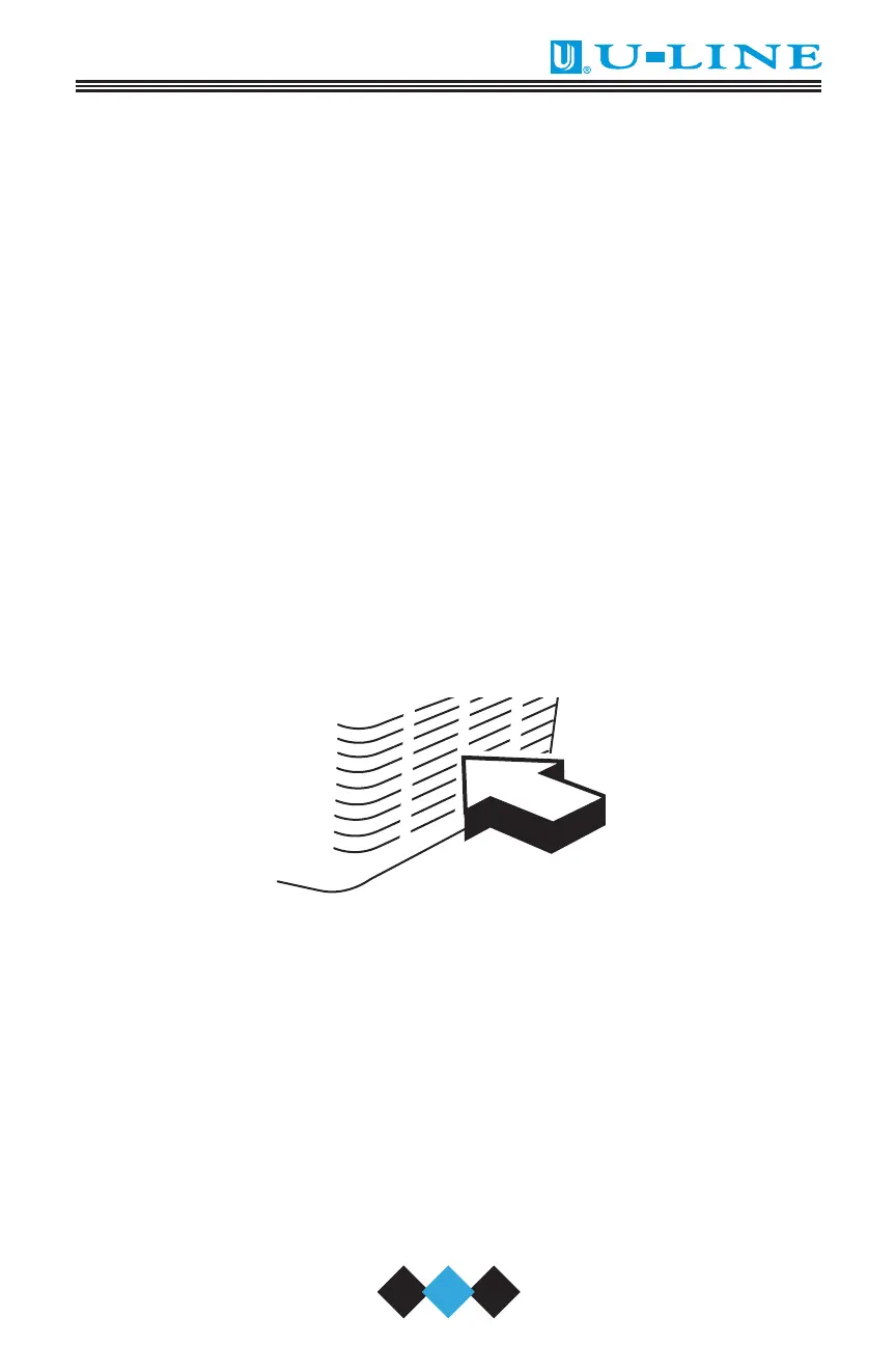
9. Position the unit to allow free air flow through the front grille
(Figure 2).
Figure 2
10. Carefully remove the grille, the glass shelves and the wine racks
from inside the unit and wipe inside of unit with a clean, water
dampened cloth only.
UL005A
30035 User Manual Body.qxd 1/5/05 1:58 PM Page 9