19
BUILT-IN INSTALLATION
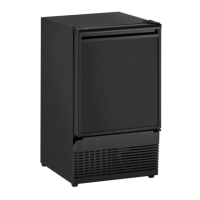
Your U-Line product is designed to be built-in or freestanding. When
built-in, they do not require additional air space for the top, sides, or
rear. However, the front grille must NOT be obstructed.
NOTE
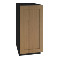
Required for ease of installation and door opening, you
must allow an additional 1/4" to width of unit.
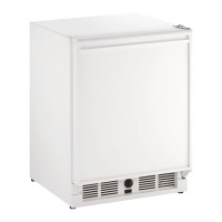
Unit Dimensions
NOTE
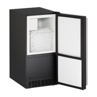
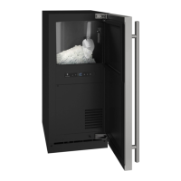
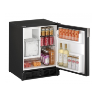
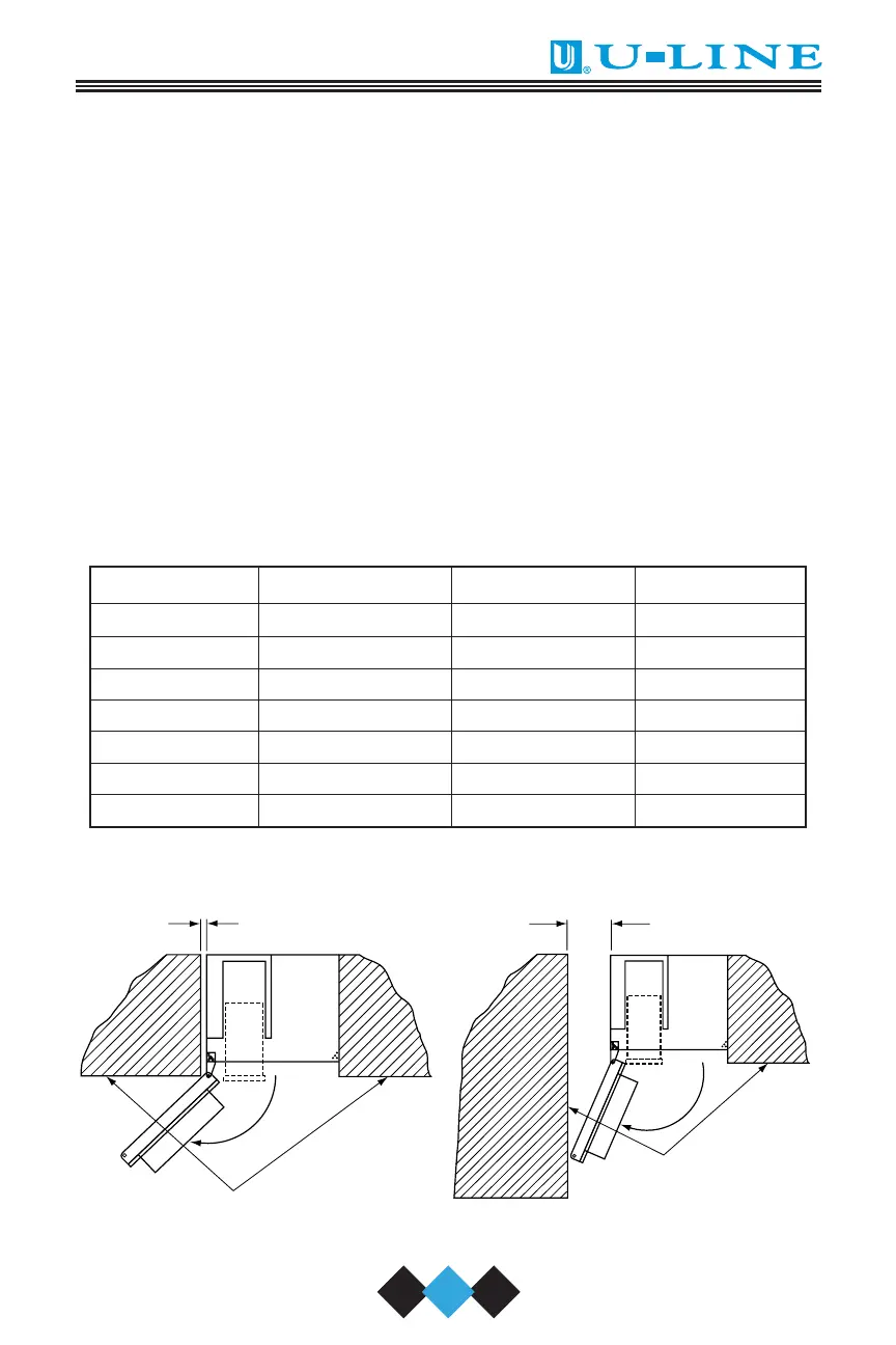
29A, 29FF Combo Models, and 75A require additional
clearance when the door opens from the right (Figures 16
and 17). This additional clearance allows for the ice bucket
to be removed from the unit.
CABINET
OR WALL
UL125
AT LEAST 9" REQUIRED IF UNIT IS
INSTALLED ADJACENT TO
CABINET OR WALL.
9.000
CABINET OR WALL
UL126
AT LEAST 1" CLEARANCE REQUIRED IF
UNIT IS INSTALLED FLUSH WITH
CABINET OR WALL.
1.000
Model Width Height Depth*
SP18 13-15/16" 18-1/2" 25-1/4"
95 13-13/16" 24-3/4" 17"
98 14-13/16" 27-3/8" 20"
15 Series 14-15/16" 34-35" 23-3/4"
29 Series 20-13/16" 28-1/2" 24"
75 Series 23-7/8" 34-35" 24"
75 BEV 23-15/16" 34-35" 24"
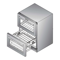
Figure 16 Figure 17
30035 User Manual Body.qxd 1/5/05 8:08 AM Page 19