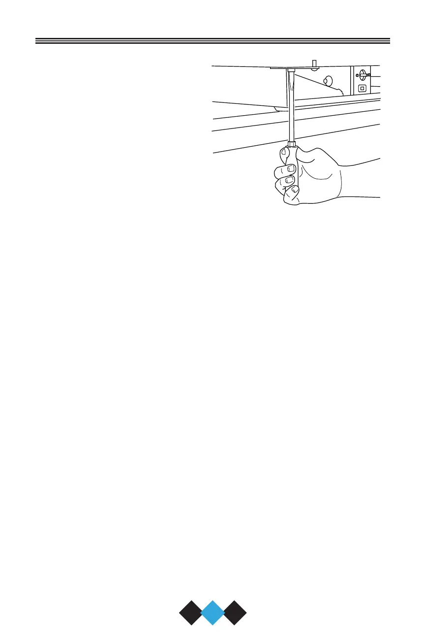
8. Install bottom hinge on cabi-
cabinet, opposite side, align-
ing flat edge of hinge with
outer edge of unit. Partially
tighten screws (Figure 32).
9. Relocate plastic spacer/
bushing on bottom of door to
opposite side (Figure 27).
Clean out bushing hole in
door bottom with a screw-
driver if needed.
10. Place door on lower hinge pin. Align flat edge of top hinge with
outer edge of unit and fasten upper hinge to unit (four screws).
Partially tighten screws until door is aligned (Figure 30).
11. Adjust door to assure proper seal. Tighten upper and lower hinge
screws securely.
12. Replace four plastic plugs removed in step 5 into holes on top of
unit. Replace screws in holes in bottom of unit, opposite side.
13. Reinspect door seal and alignment. Adjust if needed.
14. Reinstall grille (one screw).
UL129
30
User’s Manual
Figure 32
30035 User Manual Body.qxd 1/5/05 8:08 AM Page 30