ODIN-W2 series - Getting Started
UBX-15017452 - R02 Advance Information Evaluation board
Page 10 of 27
4 Evaluation board
The evaluation board for ODIN-W2 is EVK-W262.
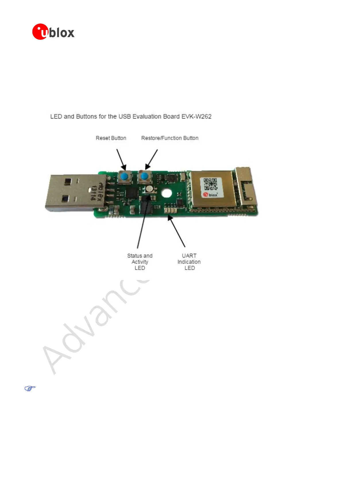
4.1 LED Indications and Buttons
There are two operational buttons and one multi LED as shown in Figure 6.
Figure 6 USB adapter board
The LED indicates what mode is currently active and what activity that is currently in progress. The following
color indications are used. See EVK-W262U Quick Start Guide [4] for more information about the EVK-W262.
The Restore/Function Button will restore to factory default with serial settings if pressed for 10 seconds during
power up. The button function will be "External connect" when ODIN-W2 is in normal mode.
• Green: The current mode is data mode or extended data mode and no connection attempts are in
progress.
• Orange: The current mode is command mode.
• Purple: A connection attempt is in progress.
• Blue: A connection is currently active.
• Blue Blinking: A connection is active and data is transmitted or received over air.
• Red Blinking: Error detected. Typically this means buffer overflow, parity or framing error detected on
the UART.
The LED on the USB adapter board is a 3-colour LED which means that, on the module, it corresponds to
three IO pins. On another board it may have different meaning.

 Loading...


