SARA-G3 and SARA-U2 series - System Integration Manual
UBX-13000995 - R26 Design-in
Page 107 of 217
2.2.1.7 Additional guidelines for VCC supply circuit design of SARA-G3 modules version “02” onward
SARA-G3 modules, versions “02” onwards, provide separate supply inputs over the VCC pins (see Figure 8):
VCC pins #52 and #53: supply input for the internal RF power amplifier, demanding most of the total
current drawn of the module when RF transmission is enabled during a voice/data call
VCC pin #51: supply input for the internal baseband PMU and transceiver, demanding minor current
SARA-G3 modules, versions “02” onwards, support two different extended operating voltage ranges: one for
the VCC pins #52 and #53, and another one for the VCC pin #51 (see the SARA-G3 series Data Sheet [1]).
All the VCC pins are in general intended to be connected to the same external power supply circuit, but separate
supply sources can be implemented for specific (e.g. battery-powered) applications considering that the voltage
at the VCC pins #52 and #53 can drop to a value lower than the one at the VCC pin #51, keeping the module
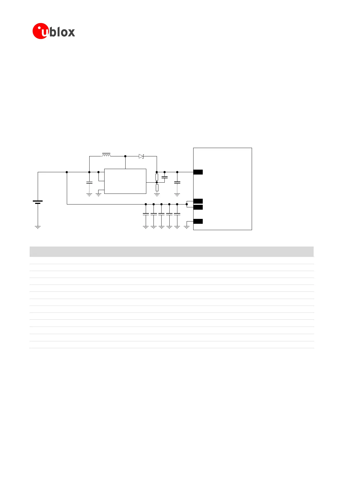
still switched-on and functional. Figure 47 describes a possible application circuit.
C1 C4
GND
C3C2 C5
SARA-G3 series
(except ‘00’, ‘01’ versions)
52
VCC
53
VCC
51
VCC
+
Li-Ion/Li-Pol
Battery
C6
SWVIN
SHDNn
GND
FB
C7
R1
R2
L1
U1
Step-up
Regulator
D1
C8
Figure 47: VCC circuit example with separate supply for SARA-G3 modules product version “02” onwards
Part Number - Manufacturer
330 µF Capacitor Tantalum D_SIZE 6.3 V 45 m
T520D337M006ATE045 - KEMET
100 nF Capacitor Ceramic X7R 0402 10% 16 V
GRM155R61A104KA01 - Murata
10 nF Capacitor Ceramic X7R 0402 10% 16 V
GRM155R71C103KA01 - Murata
56 pF Capacitor Ceramic C0G 0402 5% 25 V
GRM1555C1E560JA01 - Murata
15 pF Capacitor Ceramic C0G 0402 5% 25 V
GRM1555C1E150JA01 - Murata
10 µF Capacitor Ceramic X5R 0603 20% 6.3 V
GRM188R60J106ME47 - Murata
22 µF Capacitor Ceramic X5R 1210 10% 25 V
GRM32ER61E226KE15 - Murata
10 pF Capacitor Ceramic C0G 0402 5% 25 V
GRM1555C1E100JA01 - Murata
SS14 - Vishay General Semiconductor
10 µH Inductor 20% 1 A 276 m
SRN3015-100M - Bourns Inc.
1 M Resistor 0402 5% 0.063 W
RC0402FR-071ML - Yageo Phycomp
412 k Resistor 0402 5% 0.063 W
RC0402FR-07412KL - Yageo Phycomp
AP3015 - Diodes Incorporated
Table 29: Example of components for VCC circuit with separate supply for SARA-G3 modules product version “02” onwards
 Loading...


