SARA-G3 and SARA-U2 series - System Integration Manual
UBX-13000995 - R26 Design-in
Page 136 of 217
If only TXD, RXD, RTS, CTS and DTR lines are provided (as implemented in Figure 68 and in Figure 69) and if
HW flow-control is enabled (AT&K3, default setting), the power saving can be activated as it can be done when
the complete UART link is provided (9-wire, as implemented in Figure 66 and in Figure 67), i.e. in these ways:
AT+UPSV=1: the module automatically enters the low power idle mode whenever possible and the UART
interface is periodically enabled, as described in section 1.9.1.4, reaching low current consumption.
With this configuration, when the module is in idle mode, the data transmitted by the DTE will be buffered
by the DTE and will be correctly received by the module when active mode is entered.
AT+UPSV=3: the module automatically enters the low power idle mode whenever possible and the UART
interface is enabled by the DTR line, as described in section 1.9.1.4, reaching very low current consumption.
With this configuration, not supported only by SARA-G3 modules, when the module is in idle mode, the
UART is re-enabled 20 ms after DTR has been set ON, and the recognition of subsequent characters is
guaranteed until the module is in active mode.
If the HW flow-control is disabled (AT&K0), it is recommended to enable the power saving in one of these ways:
AT+UPSV=2: the module automatically enters the low power idle mode whenever possible and the UART
interface is enabled by the RTS line, as described in section 1.9.1.4, reaching very low current consumption.
With this configuration, when the module is in idle mode, the UART is re-enabled 20 ms after RTS has been
set ON, and the recognition of subsequent characters is guaranteed until the module is in active mode.
AT+UPSV=3: the module automatically enters the low power idle mode whenever possible and the UART
interface is enabled by the DTR line, as described in section 1.9.1.4, reaching very low current consumption.
With this configuration, not supported only by SARA-G3 modules, when the module is in idle mode, the
UART is re-enabled 20 ms after DTR has been set ON, and the recognition of subsequent characters is
guaranteed until the module is in active mode.
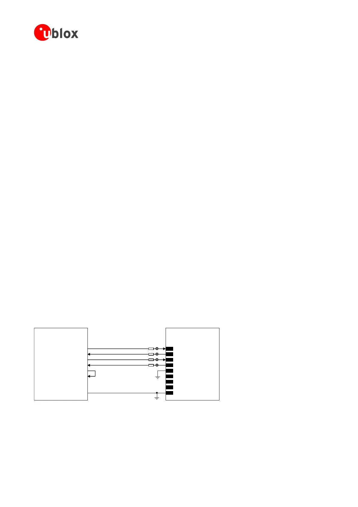
Providing the TXD, RXD, RTS and CTS lines only (not using the complete V.24 link)
If the functionality of the DSR, DCD, RI and DTR lines is not required in, or the lines are not available:
Connect the module DTR input line to GND, since the module requires DTR active (low electrical level)
Leave the DSR, DCD and RI lines of the module unconnected and floating
If RS-232 compatible signal levels are needed, the Maxim 13234E voltage level translator can be used. This chip
translates voltage levels from 1.8 V (module side) to the RS-232 standard.
If a 1.8 V Application Processor (DTE) is used, the circuit should be implemented as described in Figure 70.
TxD
Application Processor
(1.8V DTE)
RxD
RTS
CTS
DTR
DSR
RI
DCD
GND
SARA-G3 / SARA-U2
(1.8V DCE)
12
TXD
9
DTR
13
RXD
10
RTS
11
CTS
6
DSR
7
RI
8
DCD
GND
0Ω
TP
0Ω
TP
0Ω
TP
0Ω
TP
Figure 70: UART interface application circuit with partial V.24 link (5-wire) in the DTE/DCE serial communication (1.8 V DTE)
 Loading...


