SARA-G3 and SARA-U2 series - System Integration Manual
UBX-13000995 - R26 Design-in
Page 146 of 217
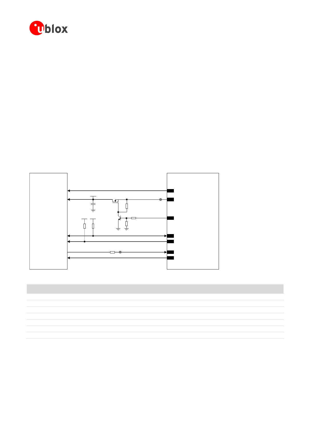
The supply of the u-blox 1.8 V GNSS receiver can be switched off using an external p-channel MOSFET
controlled by the GPIO2 pin by means of a proper inverting transistor as shown in Figure 80, implementing the
“GNSS supply enable” function. If this feature is not required, the V_INT supply output can be directly
connected to the u-blox 1.8 V GNSS receiver, so that it will be switched on when V_INT output is enabled.
The V_INT supply output provides low voltage ripple (up to 15 mVpp) when the module is in active mode or in
connected mode, but it provides higher voltage ripple (up to 90 mVpp on SARA-G3 series, or up to 70 mVpp on
SARA-U2 series) when the module is in the low power idle mode with power saving configuration enabled by
the AT+UPSV (see the u-blox AT Commands Manual [3]).
According to the voltage ripple characteristic of the V_INT supply output:
The power saving configuration cannot be enabled to use V_INT output to properly supply any 1.8 V GNSS
receiver of the u-blox 6 generation and any 1.8 V GNSS receiver of the u-blox 7 generation or any newer
u-blox GNSS receiver generation with TCXO.
The power saving configuration can be enabled to use V_INT output to properly supply any 1.8 V GNSS
receiver of the u-blox 7 generation or any newer u-blox GNSS receiver generation without TCXO.
Additional filtering may be needed to properly supply an external LNA, depending on the characteristics of
the used LNA, adding a series ferrite bead and a bypass capacitor (e.g. the Murata BLM15HD182SN1 ferrite
bead and the Murata GRM1555C1H220J 22 pF capacitor) at the input of the external LNA supply line.
SARA-G340 / SARA-G350
SARA-U2 series
u-blox GNSS
1.8 V receiver
TxD1
EXTINT0
GPIO3
GPIO4
24
25
V_BCKP V_BCKP
2
SDA2
SCL2
23
GPIO2
SDA
SCL
26
27
VCC
1V8
C1
R3
4
V_INT
R5
R4
TP
T2
T1
R1 R2
1V8 1V8
GNSS data ready
GNSS RTC sharing
GNSS supply enabled
0 Ω
TP
Figure 80: Application circuit for connecting SARA-G3 / SARA-U2 modules to u-blox 1.8 V GNSS receivers using V_INT as supply
Part Number - Manufacturer
4.7 k Resistor 0402 5% 0.1 W
RC0402JR-074K7L - Yageo Phycomp
47 k Resistor 0402 5% 0.1 W
RC0402JR-0747KL - Yageo Phycomp
10 k Resistor 0402 5% 0.1 W
RC0402JR-0710KL - Yageo Phycomp
100 k Resistor 0402 5% 0.1 W
RC0402JR-07100KL - Yageo Phycomp
P-Channel MOSFET Low On-Resistance
IRLML6401 - International Rectifier or NTZS3151P - ON Semi
100 nF Capacitor Ceramic X7R 0402 10% 16 V
GRM155R71C104KA01 - Murata
Table 51: Components for connecting SARA-G3 / SARA-U2 modules to u-blox 1.8 V GNSS receivers using V_INT as supply
For additional guidelines regarding the design of applications with u-blox 1.8 V GNSS receivers, see the GNSS
Implementation Application Note [26] and the Hardware Integration Manual of the u-blox GNSS receivers.
 Loading...


