SARA-G3 and SARA-U2 series - System Integration Manual
UBX-13000995 - R26 Design-in
Page 148 of 217
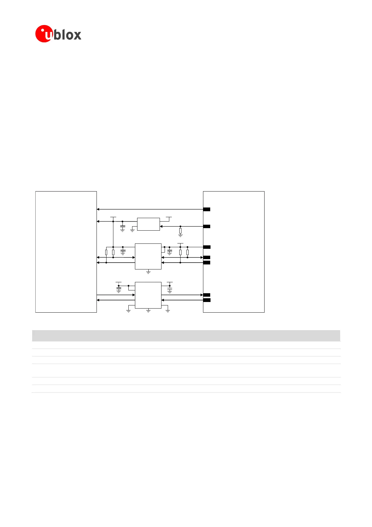
Figure 82 shows an application circuit example for connecting a SARA-U2 cellular module to a u-blox 3.0 V
GNSS receiver:
As the SDA and SCL pins of the SARA-U2 cellular module are not tolerant up to 3.0 V, the connection to
the related I
2
C pins of the u-blox 3.0 V GNSS receiver must be provided using a proper I
2
C-bus Bidirectional
Voltage Translator (e.g. TI TCA9406, which additionally provides the partial power-down feature so that the
GNSS 3.0 V supply can be ramped up before the V_INT 1.8 V cellular supply), with proper pull-up resistors.
The GPIO2 is connected to the active-high enable pin of the voltage regulator that supplies the u-blox 3.0 V
GNSS receiver providing the “GNSS supply enable” function. A pull-down resistor is provided to avoid a
switch-on of the positioning receiver when the cellular module is switched off or in the reset state.
As the GPIO3 and GPIO4 pins of the SARA-U2 cellular modules are not tolerant up to 3.0 V, the connection
to the related pins of the u-blox 3.0 V GNSS receiver must be provided using a proper Unidirectional General
Purpose Voltage Translator (e.g. TI SN74AVC2T245, which additionally provides the partial power down
feature so that the 3.0 V GNSS supply can be also ramped up before the V_INT 1.8 V cellular supply).
The V_BCKP supply output of the cellular module can be directly connected to the V_BCKP backup supply
input pin of the GNSS receiver as in the application circuit for a u-blox 1.8 V GNSS receiver.
u-blox GNSS
3.0 V receiver
24
GPIO3
1V8
B1 A1
GND
U3
B2A2
VCCBVCCA
Unidirectional
Voltage Translator
C4
C5
3V0
TxD1
R1
INOUT
GNSS LDO Regulator
SHDNn
R2
VMAIN3V0
U1
23
GPIO2
26
SDA
27
SCL
R4 R5
1V8
SDA_A SDA_B
GND
U2
SCL_ASCL_B
VCCA
VCCB
I2C-bus Bidirectional
Voltage Translator
4
V_INT
C1
C2 C3
R3
SDA2
SCL2
VCC
DIR1
DIR2
2
V_BCKPV_BCKP
OEn
OE
GNSS data ready
GNSS supply enabled
GND
SARA-U2 series
EXTINT0 GPIO4
25
GNSS RTC sharing
Figure 82: Application circuit for connecting SARA-U2 modules to u-blox 3.0 V GNSS receivers
Part Number - Manufacturer
4.7 kΩ Resistor 0402 5% 0.1 W
RC0402JR-074K7L - Yageo Phycomp
47 kΩ Resistor 0402 5% 0.1 W
RC0402JR-0747KL - Yageo Phycomp
100 nF Capacitor Ceramic X5R 0402 10% 10V
GRM155R71C104KA01 - Murata
Voltage Regulator for GNSS receiver and related
output bypass capacitor
See GNSS receiver Hardware Integration Manual
I2C-bus Bidirectional Voltage Translator
TCA9406DCUR - Texas Instruments
Generic Unidirectional Voltage Translator
SN74AVC2T245 - Texas Instruments
Table 53: Components for connecting SARA-U2 modules to u-blox 3.0 V GNSS receivers
For additional guidelines regarding the design of applications with u-blox 3.0 V GNSS receivers, see the GNSS
Implementation Application Note [26] and the Hardware Integration Manual of the u-blox GNSS receivers.
2.6.4.2 Guidelines for DDC (I
2
C) layout design
The DDC (I
2
C) serial interface requires the same consideration regarding electro-magnetic interference as any
other digital interface. Keep the traces short and avoid coupling with RF line or sensitive analog inputs, since the
signals can cause the radiation of some harmonics of the digital data frequency.
 Loading...


