SARA-G450 - System integration manual
UBX-18046432 - R08 Design-in Page 103 of 143
C1-Public
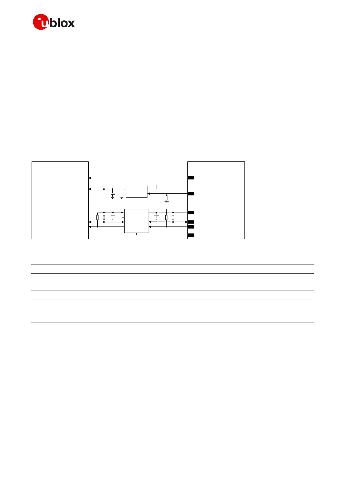
If SARA-G450 module’s generic digital interfaces are configured to operate at 3.0 V (V_INT = 3 V, if
VSEL pin is left unconnected; see 1.5.3), Figure 65 shows an application circuit example for connecting
the cellular module to a u-blox 1.8 V GNSS receiver:
As the SDA2 and SCL2 pins of the u-blox GNSS receiver may not be tolerant up to 3.0 V, the
connection to the related I2C pins of the SARA-G450 module must be provided using an
appropriate I2C-bus bidirectional voltage translator (e.g. TI TCA9406, which additionally provides
the partial power-down feature), with suitable pull-up resistors.
The GPIO2 is connected to the active-high enable pin of the voltage regulator that supplies the
u-blox 1.8 V GNSS receiver providing the “GNSS supply enable” function. A pull-down resistor is
provided to avoid a switch-on of the positioning receiver when the cellular module is switched off
or in reset state.
The V_BCKP supply output of the cellular module can be directly connected to the V_BCKP supply
input pin of the GNSS receiver as in the application circuit of Figure 63.
u-blox GNSS
1.8 V receiver
R1
INOUT
GNSS LDO
regulator
SHDN
R2
VMAIN1V8
U1
23
GPIO2
26
SDA
27
SCL
R4 R5
3V0
SDA_B
SDA_A
GND
U2
SCL_B
SCL_A
VCCB
VCCA
I2C-bus bidirectional
voltage translator
4
V_INT
C1
C2 C3
R3
SDA2
SCL2
VCC
2
V_BCKPV_BCKP
OE
GNSS supply enable
GND
SARA-G450
(3.0 V)
21
VSEL
Figure 65: Application circuit for connecting SARA-G450 (3.0 V) modules to u-blox 1.8 V GNSS receivers
Part number - Manufacturer
4.7 kΩ resistor 0402 5% 0.1 W
RC0402JR-074K7L - Yageo Phycomp
47 kΩ resistor 0402 5% 0.1 W
RC0402JR-0747KL - Yageo Phycomp
100 nF capacitor ceramic X5R 0402 10% 10V
GRM155R71C104KA01 - Murata
Voltage regulator for GNSS receiver and related
output bypass capacitor
See GNSS receiver hardware integration manual
I2C-bus bidirectional voltage translator
TCA9406DCUR - Texas Instruments
Table 39: Components for connecting SARA-G450 (3.0 V) modules to u-blox 1.8 V GNSS receivers
For additional guidelines regarding the design of applications with u-blox 1.8 V GNSS receivers, see
the GNSS implementation application note [22] and the hardware integration manual of the u-blox
GNSS receivers.

 Loading...