SARA-G450 - System integration manual
UBX-18046432 - R08 System description Page 23 of 143
C1-Public
1.6.1.2 Switch-on sequence from power-off mode
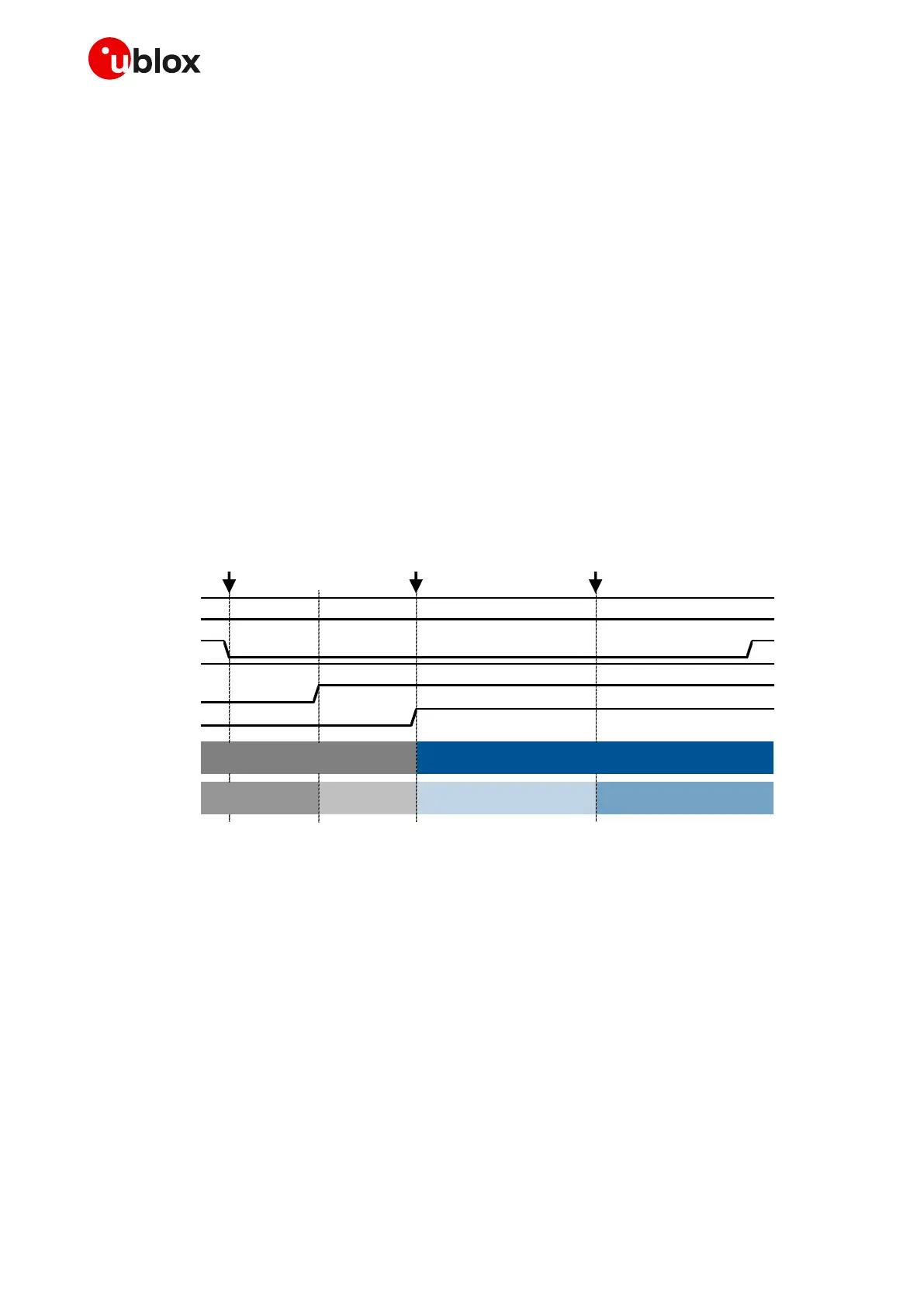
Figure 12 shows the power-on sequence from the power-off mode, describing the following phases:
The external supply is still applied to the VCC inputs. The V_BCKP output is internally enabled
since an appropriate VCC is present. The PWR_ON and PWR_OFF pins are set to high logic level
due to internal pull-ups.
The PWR_ON input pin is set low for a valid time period, representing the start-up event.
All the generic digital pins of the module are tri-stated until the switch-on of their supply source
(V_INT): any external signal connected to the generic digital pins must be tri-stated or set low at
least until the activation of the V_INT supply output to avoid latch-up of circuits and allow a clean
boot of the module.
The V_INT generic digital interfaces supply output is enabled by the integrated Power
Management Unit.
The Internal Reset signal is held low by the integrated Power Management Unit: the baseband
processor core and all the digital pins of the modules are held in reset state.
When the Internal Reset signal is released by the integrated Power Management Unit, any digital
pin is set in a correct sequence from the reset state to the default operational state.
The module is fully ready to operate after all the interfaces are configured.
VCC
V_BCKP
PWR_ON
PWR_OFF
V_INT
Internal reset
System state
Digital pins state
Internal reset → Operational
Start of interface
configuration
Module interfaces
are configured
Figure 12: SARA-G450 modules power-on sequence from power-off mode
1.6.1.3 General considerations for the switch-on procedure
A greeting text can be activated by means of the +CSGT AT command (see the u-blox AT commands
manual [11]) to notify the external application that the module is ready to operate (i.e. ready to reply to
AT commands) and that the first AT command can be sent to the module. In this case, the UART
autobauding must be disabled to let the module send the greeting text: the UART must be configured
at a fixed baud-rate (the baud-rate of the application processor) instead of the default autobauding,
otherwise the module does not know the baud-rate to be used for sending the greeting text (or any
other URC) at the end of the internal boot sequence.
As an alternative starting procedure, after the interfaces’ configuration phase, the application can
start sending AT commands and wait for the response with a 30 s timeout; iterate it 4 times without
resetting or removing the VCC supply of the module, and then run the application.

 Loading...