SARA-G450 - System integration manual
UBX-18046432 - R08 Design-in Page 96 of 143
C1-Public
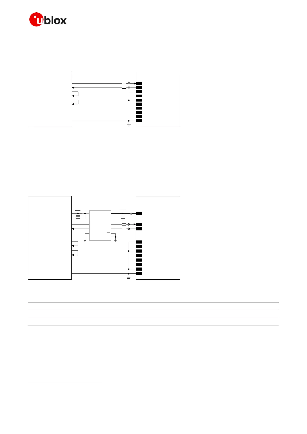
If a 3.0 V application processor (DTE) is used and module (DCE) generic digital interfaces are
configured to operate at 3.0 V (V_INT = 3 V, if VSEL pin is left unconnected; see 1.5.3), the circuit
should be implemented as described in Figure 57.
TxD
Application Processor
(3.0V DTE)
RxD
RTS
CTS
DTR
DSR
RI
DCD
GND
SARA-G450
(3.0V DCE)
12
TXD
9
DTR
13
RXD
10
RTS
11
CTS
6
DSR
7
RI
8
DCD
GND
0Ω
TP
0Ω
TP
21
VSEL
Figure 57: UART application circuit with partial V.24 link (3-wire) in the DTE/DCE serial interface (3.0 V DTE / 3.0 V DCE)
If a 3.0 V application processor (DTE) is used and module (DCE) generic digital interfaces are
configured to operate at 1.8 V (V_INT = 1.8 V, if VSEL pin is connected to GND; see 1.5.3), then it is
recommended to connect the 1.8 V UART interface of the module (DCE) by means of appropriate
unidirectional voltage translators using the module V_INT output as the 1.8 V supply for the voltage
translators on the module side, as described in Figure 58.
4
V_INT
TxD
Application Processor
(3.0V DTE)
RxD
DTR
DSR
RI
DCD
GND
SARA-G450
(1.8V DCE)
12
TXD
9
DTR
13
RXD
6
DSR
7
RI
8
DCD
GND
1V8
B1 A1
GND
U1
VCCB
VCCA
Unidirectional
voltage translator
C1
C2
3V0
DIR1
DIR2 OE
VCC
B2 A2
RTS
CTS
10
RTS
11
CTS
TP
0Ω
TP
0Ω
TP
21
VSEL
Figure 58: UART application circuit with partial V.24 link (3-wire) in the DTE/DCE serial interface (3.0 V DTE / 1.8 V DCE)
Part number – Manufacturer
100 nF capacitor ceramic X7R 0402 10% 16 V
GRM155R61A104KA01 – Murata
Unidirectional voltage translator
SN74AVC2T245
17
- Texas Instruments
Table 35: Parts for UART application circuit with partial V.24 link (3-wire) in DTE/DCE serial interface (3.0 V DTE / 1.8 V DCE)
☞ If only the TXD and RXD lines are provided, data delivered by the DTE can be lost with module
power saving enabled by AT+UPSV=1
Voltage translator providing partial power-down feature so that the DTE 3.0 V supply can be also ramped up before V_INT
1.8 V supply

 Loading...