SARA-R5 series - System integration manual
UBX-19041356 - R04 Design-in Page 64 of 118
C1-Public
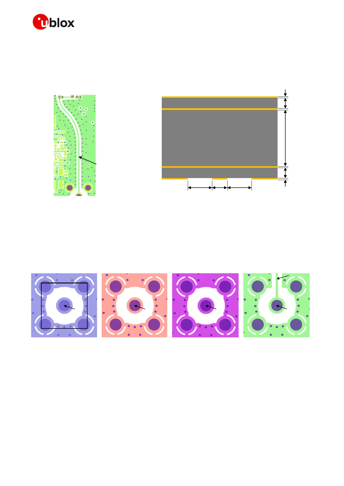
After the antenna detection circuit with the layout illustrated on the left side of Figure 39, the antenna
RF trace is designed as a 50 grounded coplanar waveguide on the bottom layer of the u-blox host
printed circuit board, with total length ~29 mm, with layout and thickness, width, gap (signal to
ground) characteristics illustrated in Figure 40. Guidelines to design a proper equivalent 50
transmission line on a host printed circuit board are available in section 2.4.1.2.
RF trace
Bottom layer (L4) layout
35 µm
35 µm
35 µm
35 µm
220 µm
220 µm
1200 µm
L1 copper
L3 copper
L2 copper
L4 copper
FR-4 dielectric
FR-4 dielectric
FR-4 dielectric
PCB stack-up structure
310 µm 500 µm500 µm
L1 C1
D1
Figure 40: 50 grounded coplanar waveguide transmission line designed on the u-blox host PCB bottom layer
The 50 grounded coplanar waveguide routed on the bottom layer is terminated on a dedicated 50
SMA female connector mounted on the top layer, consisting in the cellular RF input/output of the host
PCB for external antenna and/or RF coaxial cable access, with board layout illustrated in Figure 41.
Guidelines to design a proper equivalent 50 termination on a host printed circuit board are available
in section 2.4.1.3, with antenna selection and design guidelines available in section 2.4.2.1.
Top layer (L1) Layout L2 layout L3 layout Bottom layer (L4) layout
RF trace
L1-L4 viaL1-L4 via L1-L4 via L1-L4 via
SMA
Figure 41: 50 SMA female connector layout on the u-blox host PCB
The 50 characteristic impedance of the antenna trace design on a host printed circuit board can be
verified using a Vector Network Analyzer, as done on the u-blox host PCB, with calibrated RF coaxial
cable soldered at the pad corresponding to RF input/output of the module and with the transmission
line terminated to a 50 load at the 50 SMA female connector.
Compliance of the design with regulatory rules and specifications defined by the FCC, ISED, RED, etc.
can be verified using a radio communication tester (callbox) as the Rohde & Schwarz CMW500, or any
equivalent equipment for multi-technology signaling conformance tests.

 Loading...


