ZED-F9K-Integration manual
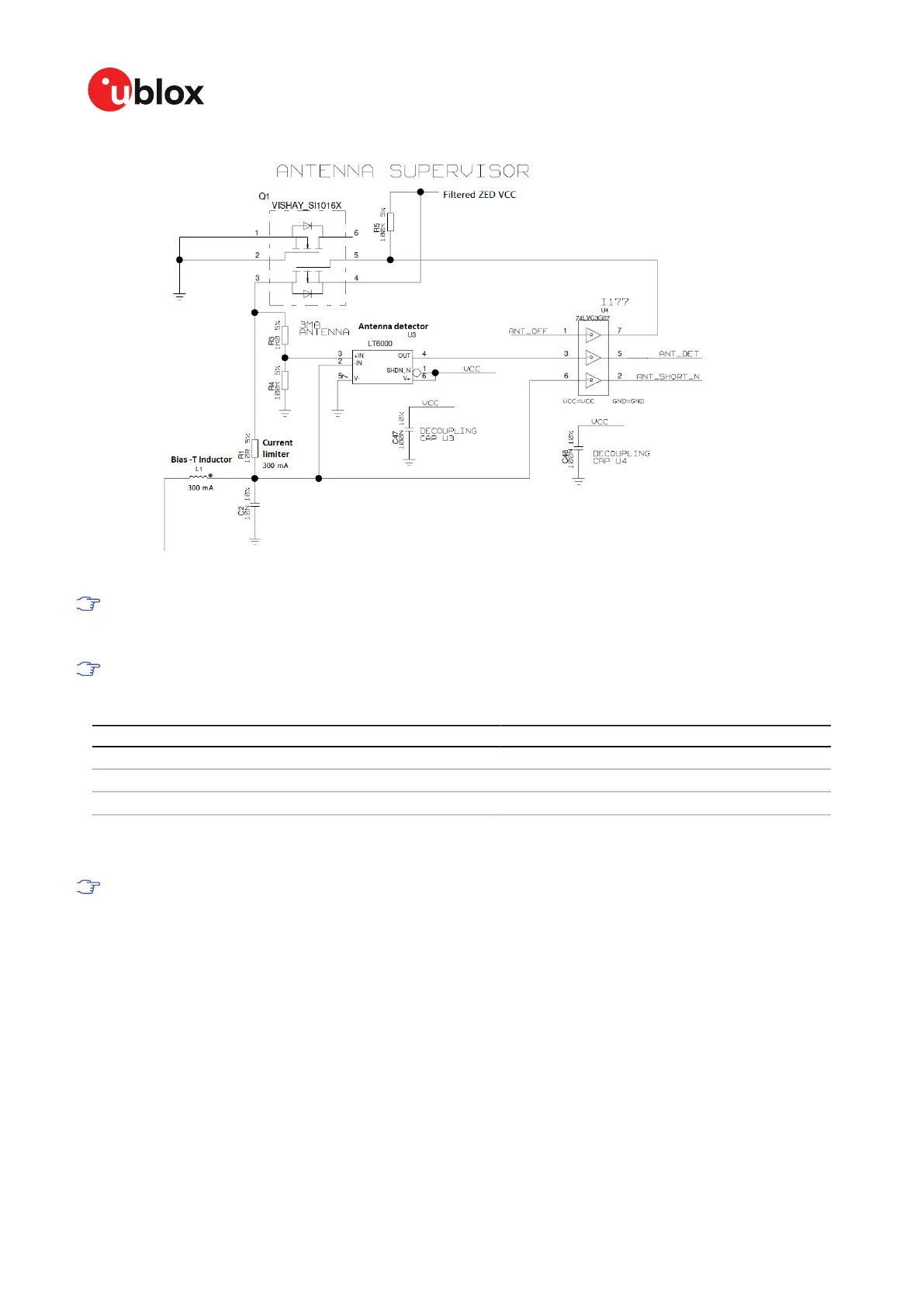
Figure 18: ZED-F9K antenna supervisor
The bias-t inductor must be chosen for multi-band operation; a value of 47 nH ±5% is
required for our recommended Murata part, with the current limited below its 300 mA
rating. See Antenna bias section for additional information.
Circuit shows buffer [U4]. Buffer is not strictly necessary when supplied from VCC. It is only
required when supplying antenna voltage that is not obtained from or controlled by module
VCC or VCC_RF .
Part Recommendation Comment
L1 Murata LQG15HS47NJ02/47N 300mA and >500 Ω at L band frequencies
C2 Murata GRM033R71C103KE14 CAP CER X7R 0402 10N 10% 16V
TYCO, 0.25PF, PESD0402-140 -55/+125C ESD protection diode on RF trace
Table 17: Recommended components for antenna supervisor
3.6.1 Antenna voltage control - ANT_OFF
Antenna status (as reported in UBX-MON-RF and UBX-INF-NOTICE messages) is not
reported unless the antenna voltage control has been enabled.
Enable the antenna voltage control by setting the configuration item CFG-HW-
ANT_CFG_VOLTCTRL to true (1).
Result:
• UBX-MON-RF in u-center "Message View": Antenna status = OK. Antenna power status = ON
• ANT_OFF pin = active high to turn antenna off therefore the pin is low to enable an external
antenna.
Start-up message at power up if configuration stored:
$GNTXT,01,01,02,ANTSUPERV=AC *00
$GNTXT,01,01,02,ANTSTATUS=INIT*3B
UBX-20046189 - R01
3 Receiver functionality Page 45 of 105
C1-Public Early production information

 Loading...


