ZED-F9K-Integration manual
The antenna system should include filtering to ensure adequate protection from nearby
transmitters. Take care in the selection of antennas placed close to cellular or Wi-Fi transmitting
antennas.
4.5.1 Antenna bias
Active antennas have an integrated low-noise amplifier that contributes an additional current of
typically 5 to 20 mA to the system's power consumption budget.
If customers do not want to make use of the antenna supervisor function the filtered VCC_RF supply
voltage output can supply the antenna if the supply voltage of the ZED-F9K module matches the
antenna working voltage (e.g. 3.0 V).
A series current limiting resistor is required to prevent short circuits destroying the bias-t
inductor.
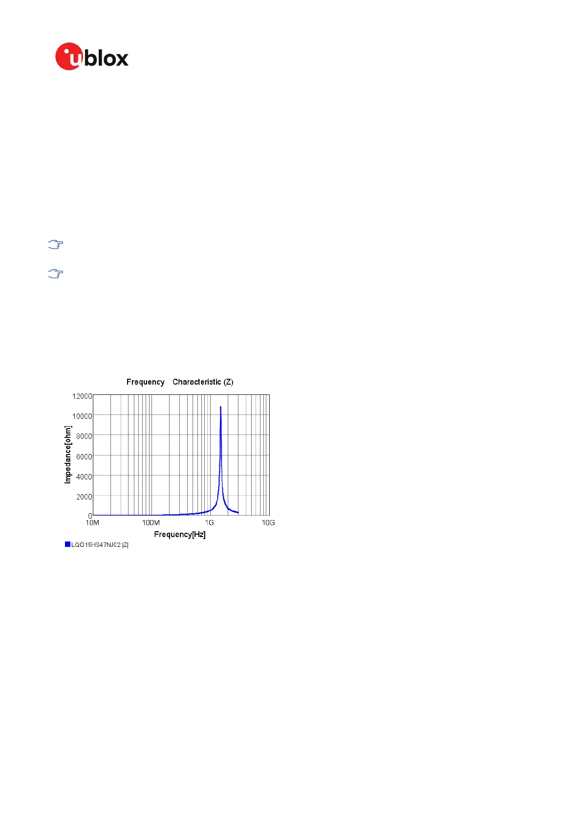
The bias-t inductor must be chosen for multi-band operation, a value of 47 nH ±5% is
recommended for the recommended Murata L part. It has a self-resonance frequency of 1
GHz and a high impedance (> 500 Ω) at L band frequencies.
The recommended bias-t inductor (Murata LQG15HS47NJ02) has a maximum current capacity of
300 mA. Hence the current is limited to 70 mA at 3.3V using an active limiter in the recommended
circuit shown in Figure 37 below. A 10 Ω resistor (R2) is provided to measure the current. This resistor
power rating must be chosen to ensure reliability in the chosen circuit design.
Figure 36: ZED-F9K antenna bias inductor impedance
A recommended circuit design for an active antenna bias is shown below. This example shows an
external voltage of 3.3 V with current limiting as described above. An ESD protection diode should
also be connected to the input as shown.
UBX-20046189 - R01
4 Design Page 79 of 105
C1-Public Early production information

 Loading...


