ZED-F9K-Integration manual
4.8.3.2 Paste mask
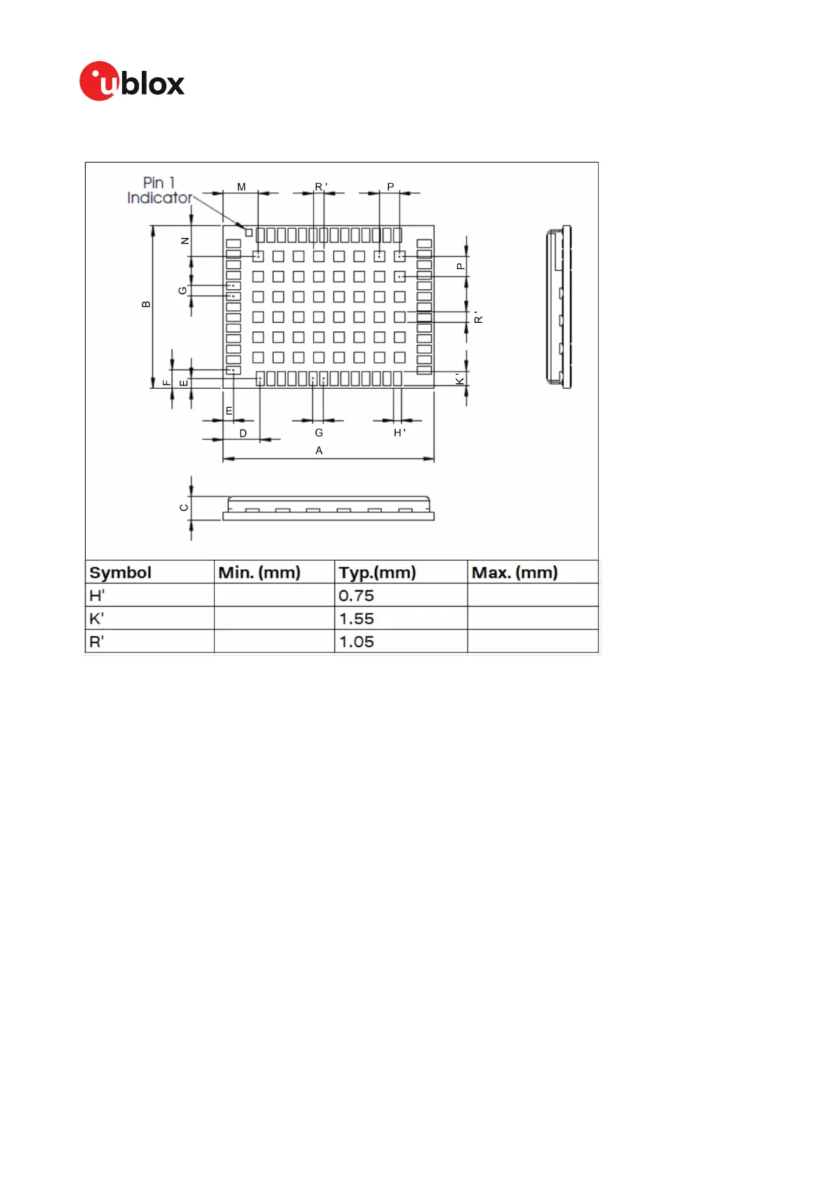
Figure 43: ZED-F9K suggested paste mask
4.8.4 Layout guidance
The presented layout guidance reduces the risk of performance issues at design level.
4.8.4.1 RF In trace
The RF in trace has to work in the combined GNSS signal bands.
For FR-4 PCB material with a dielectric permittivity of for example 4.7, the trace width for the 50 Ω
line impedance can be calculated.
A grounded co-planar RF trace is recommended as it provides the maximum shielding from noise
with adequate vias to the ground layer.
The RF trace must be shielded by vias to ground along the entire length of the trace and the ZED-
F9K RF_IN pad should be surrounded by vias as shown in the figure below.
UBX-20046189 - R01
4 Design Page 86 of 105
C1-Public Early production information

 Loading...


