7
Page.
/ 8
Reassembly
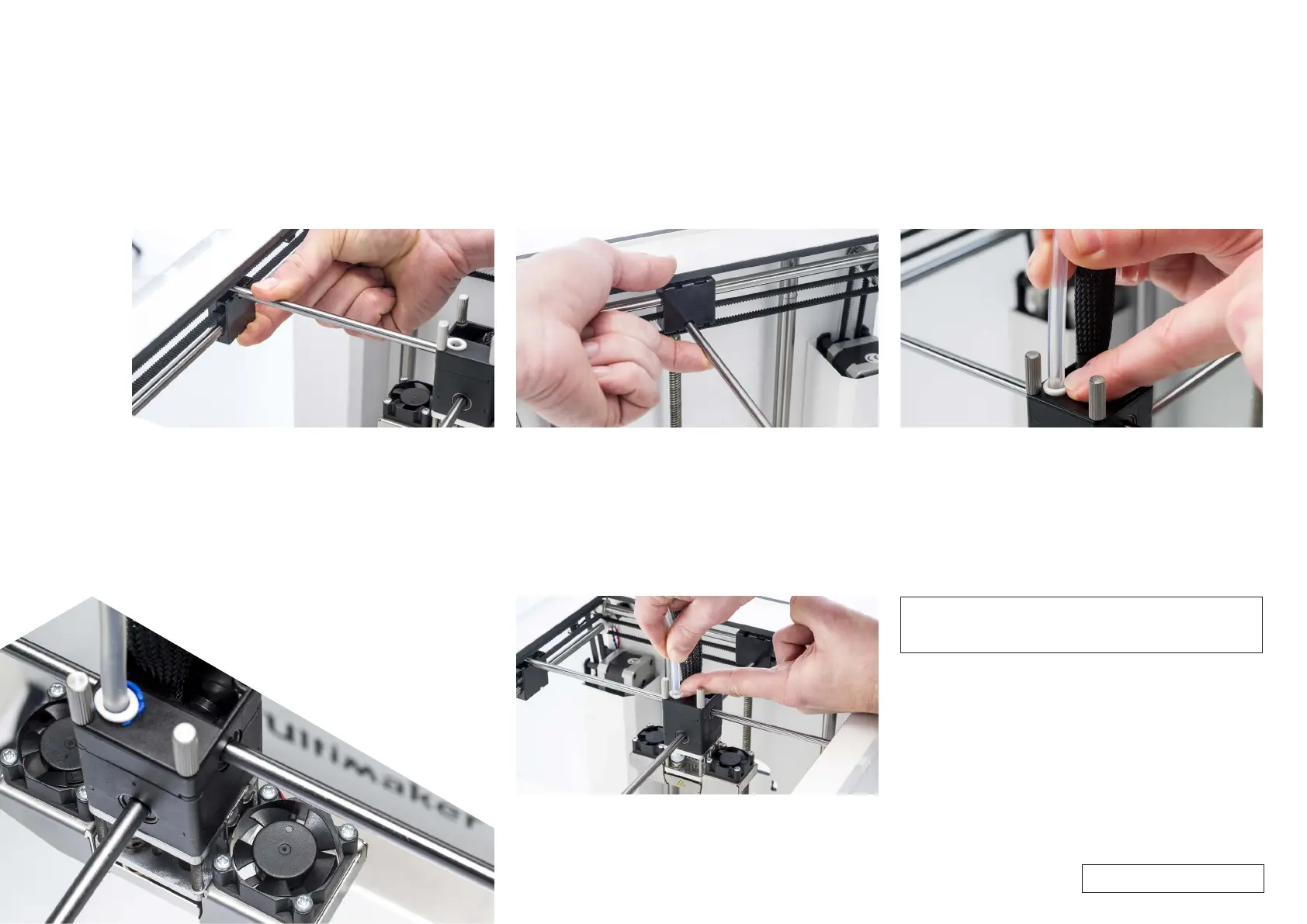
14. Secure the print head shaft X
• Tilt the left and right sliding blocks to be able to place the print
head shaft X in the notch. Make sure that the end of the shaft is 1
mm from the left panel.
• While supporting the bottom of the sliding block, push down on
the end of the shaft until it clicks into place. Do this for both sides.
Tip: Check if the print head shaft X is activating the Y limit switch.
If not, remove the print head shaft X and click it in place further to the
left.
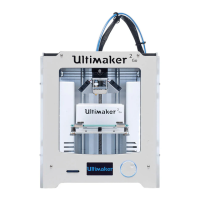
15. Secure the print head shaft Y
• Tilt the front and back sliding blocks to be able to place the print
head shaft Y in the notch. Make sure that the shaft is exactly in the
middle.
• Pull the end of the axle upwards until it clicks into place. Do this for
both sides.
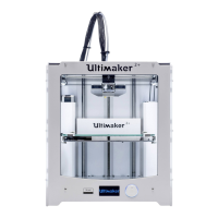
16 Insert the Bowden tube
• Press down on the tube coupling collet in the print head.
• Push the Bowden tube all the way in.
Tip: Check if all four sliding blocks are completely upright and not
tilted.
Tip: To avoid bending the print head shafts, it is recommended to
place the print head in the corner before inserting the Bowden tube.
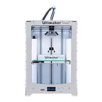
17. Ensure the Bowden tube is correctly inserted
• Let go of the tube coupling collet and gently pull the Bowden tube,
along with the tube coupling collet, approximately 2 mm upwards.
• Hold the tube coupling collet up with your fingernail.
• While holding the tube coupling collet up, push the Bowden tube
down again.
Note: This step ensures that the end of the Bowden tube connects
correctly to the TFM coupler. This prevents room between the
parts as well as play on the Bowden tube.
For internal use only