Service Manual UDP6900 Series Digital Control Power Supply
Instruments.uni-trend.com 17 / 29
5. Removal and Replacement
Disassembly/Replacement Tool
Use the tool is shown in the following table to replace the module of the digital power supply.
The model refers to the removal steps
For removing BNC socket or input jack
For protect the screen and rotary knob when removing rear modules
To prevent static damage to the components while working on the
instrument, wear properly grounded anti-static wristbands and foot
bands, and use anti-static pads in a tested anti-static environment
Flat head screwdriver
with plastic handle
For removing the fuse socket
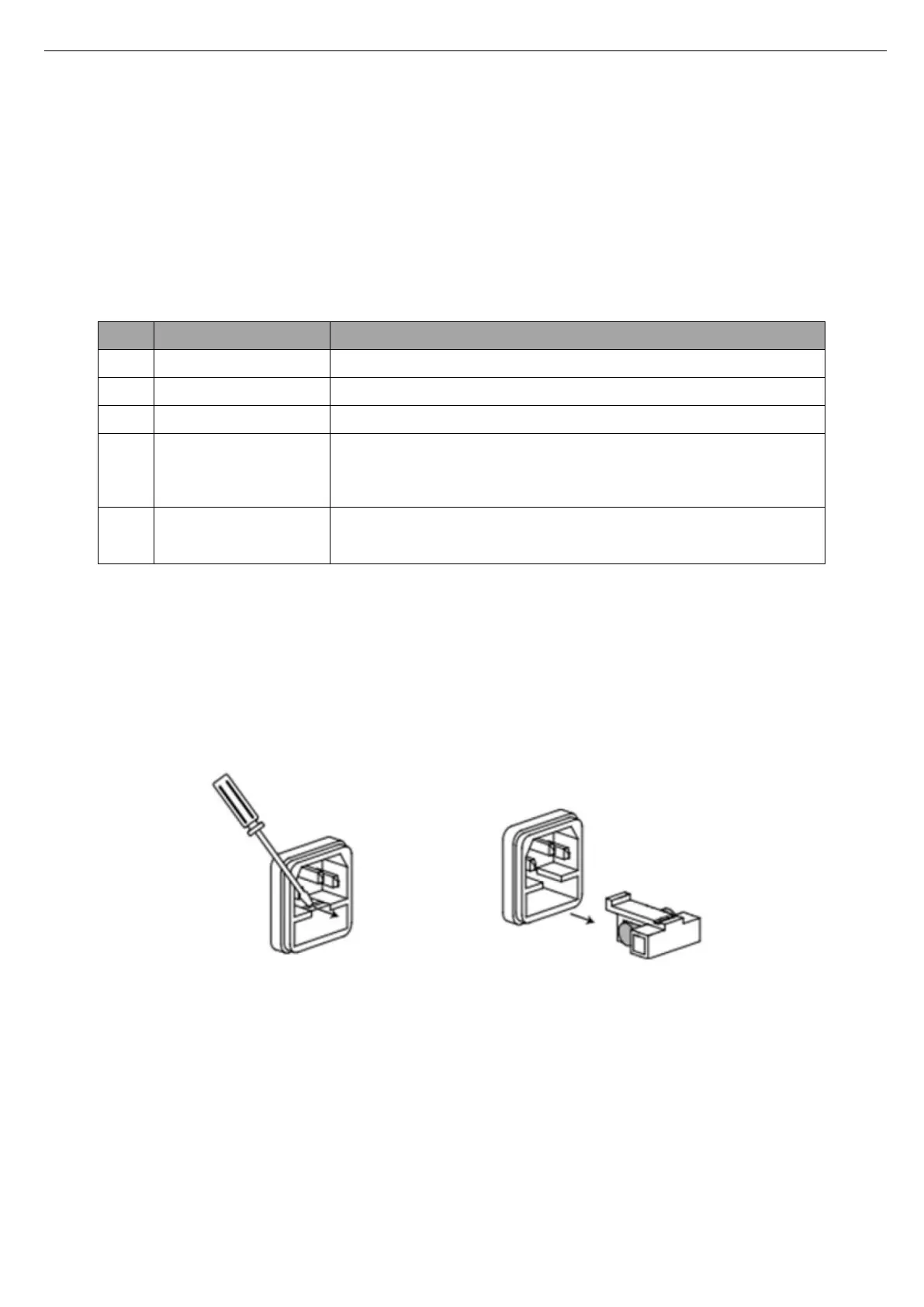
Replace Fuse
This instrument has 1 spare fuse stored in the fuse box. If the fuse was burned out, replace the fuse as the
follow steps.
1) Pull out the power cable, use small screwdriver to take out the fuse box, as shown in the following figure.
If the fuse was burned out, please replace the same specification fuse with the instrument.
The specification fuse with the instrument, see the following table.
 Loading...