Do you have a question about the UNI-T UT3200 Series and is the answer not in the manual?
Introduction to the product manual and safety advice.
Details about UNI-T's trademark, rights, and warranty terms.
Essential guidelines for safe operation and avoiding electric shock.
Cautions against exceeding voltage limits and information on EFUP/WEEE.
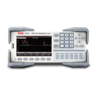
Lists UT3200 series models: UT3208, UT3216, UT3224, UT3232.
Highlights LCD display, thermocouple inputs, and wide application fields.
Details display types, test ranges, thermocouple inputs, and core functionalities.
Covers FAT storage, RS232/USB interfaces, language, and environmental specs.
Identifies buttons and indicators on the front panel of the UT3208 example.
Describes On/Off, F1-F6, Esc, Print Sc, Test, Setup, LOCK, and cursor button functions.
Details the numeric keypad for input and the USB interface.
Explains symbols for data saving, alarms, comparator, lock, and temperature units.
Identifies RS232, USB ports, AC socket, and data acquisition modules.
Lists all included items and checks for damage or missing parts.
Specifies voltage (100-240VAC), frequency (50/60Hz), and power (10VA).
Defines operating temperature (10-40°C), humidity (10-90%RH), and altitude.
Guidelines for cleaning the instrument and adjusting the lift handle.
Guides on connecting the power line and turning on the instrument for testing.
Details on connecting K-type thermocouple test lines and 8-way modules.
Step-by-step guide for connecting test leads to the instrument's data collect port.
How to use channel identification stickers to label test lines.
Describes the mapping of data acquisition modules to channel numbers (CH01-CH32).
Using 8G USB for recording, file formats, and basic operation steps.
How to use the Test button to display and collect data numerically.
Instructions for turning specific channels on/off to manage data display.
Viewing temperature trends over time using the curve graph display.
How to set upper and lower limits for the curve graph's vertical axis.
Explains how speed settings affect the horizontal axis time scale.
Details functions like Stop, Return, Zoom, Shift, and Trace for curve analysis.
Explains the default automatic histogram mode for comparing channel temperatures.
Displays histograms for negative, mixed, and out-of-range temperature values.
How to use manual mode for histogram to visualize temperature deviations.
USB recording timing, file structure, and internal clock dependency.
Details on file name, product info, channel temp data, and CSV format.
How to capture and save screenshots to USB drive.
Initial steps for configuring the comparator for temperature alarms.
Detailed procedure to open comparator, set limits, and enable audible alarms.
How to set high/low temperature limits and thermocouple types per channel.
How to choose between slow (1s) and fast (0.5s) data collection rates.
How to select temperature units: Celsius, Kelvin, or Fahrenheit.
How to turn the audible key beep sound on or off.
How to set a file name prefix for data saved to USB.
How to set time intervals for automatic file creation during USB recording.
Details on setting the DELAY or record time interval for USB recording.
Relates to setting channel model names, limits, and thermocouple types.
Function for adjusting abnormal temperature readings, used for calibration.
Steps for entering amendment values and resetting calibration data.
Section for configuring system-wide settings like language and account.
How to access the System Config menu via the Setup shortcut.
How to choose between Chinese (CHS) and English for the display language.
Step-by-step guide for setting the instrument's internal date and time.
Describes ADMIN/USER modes and procedures for changing/deleting passwords.
How to set communication modes (RS232/USB) and baud rates.
Recommended baud rates for opto-isolator and high-speed computer communication.
Displays model, sensor type, channel amount, SW version, and serial number.
Warning regarding the use of the calibration function and potential data loss.
Accessing the file management page for saving/recalling settings.
Steps for saving, recalling, and deleting current instrument settings.
How to connect and use the RS-232 DB-9 serial interface with external devices.
Data bits, stop bit, parity, and baud rate recommendations for RS-232.
How to use the USB interface for communication when RS232 is unavailable.
Steps to activate USB communication via SYSTEM CONFIG > COM MODE.
Guide to downloading and installing the CH340 USB driver from the UNI-T website.
How to find the assigned COM port number in Device Manager for communication.
Information on the instrument's support for SCPI language commands.
| Brand | UNI-T |
|---|---|
| Model | UT3200 Series |
| Category | Thermometer |
| Language | English |