UTD2000 Series User Manual
31
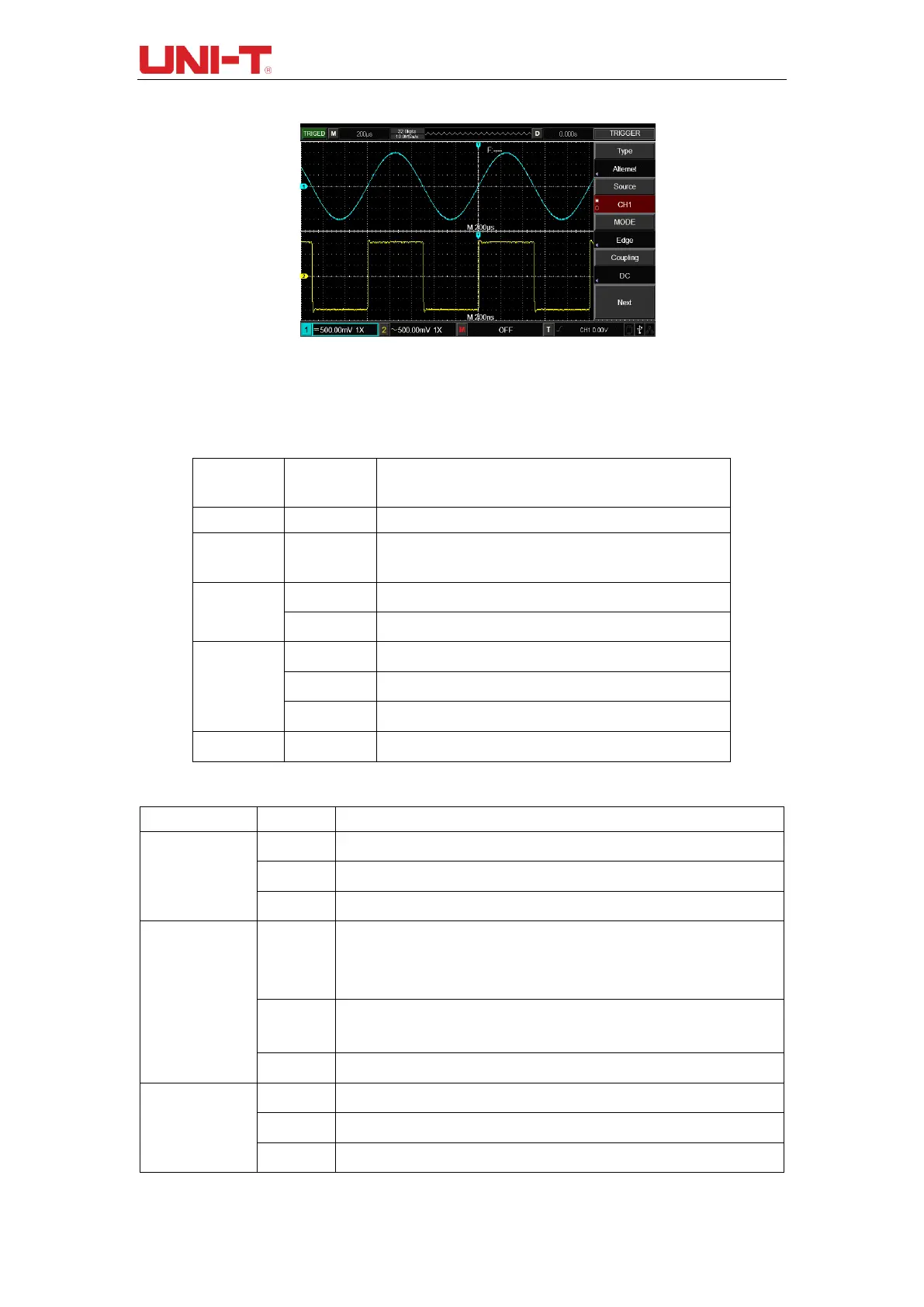
Figure 4-3 Observing Signals with Two Different Frequencies by
Alternating Trigger Mode
Table 4-7 Alternating Trigger Menu (Page 1)
CH1 and CH2 alternating trigger
Select CH1 as current channel
Select CH2 as current channel
Set the edge as trigger mode
Set the pulse width as trigger mode
Set the slope as trigger mode
Set trigger on the signal rising edge.
Set trigger on the signal falling edge.
Set trigger on the signal both rising and falling edge.
When there is no signal input, the system will automatically collect waveform
data and the scan base line will be displayed on the screen. When there is
signal input, the system will automatically switch to trigger scan.
Stop collecting data when there is no trigger signal, the system will conduct
trigger scan when the trigger signal generates.
The DSO will only perform 1 cycle of triggering when there is triggering signal.
Pass through DC and AC components of triggering signal.
Block the DC component of triggering signal.
Reject high-frequency component of the triggering signal.
 Loading...


