UTG1000A Series 63
Duty cycle deviation is limited by the minimal duty cycle of pulse wave and current edge time.
Comprehensive Example
Make the instrument work in pulse modulation (PWM) mode, then set a sine wave with 1kHz from the internal of
the instrument as a modulation signal and a pulse wave with 10kHz frequency, 2Vpp amplitude and 50% duty cycle
as a carrier wave signal, finally, set duty cycle deviation to 40%. Specific steps are seen as following:
1) Enable Pulse Width Modulation (PWM) Function
Press Menu→Modulation→Type→Pulse Width Modulation in turn to start the PWM function.
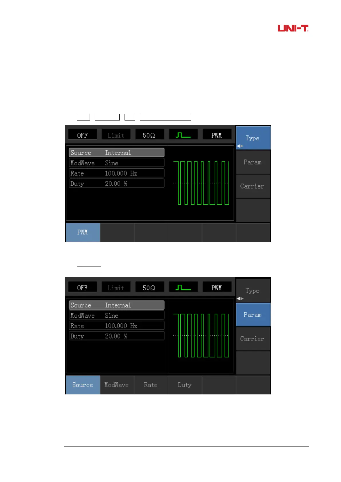
2) Set Modulation Signal Parameter
Press Parameter softkey and the interface will show as following:
Press corresponding softkey, then enter required numerical value, and select the unit.
 Loading...