User’s Manual UTG1000X Series
Instruments.uni-trend.com 15 / 74
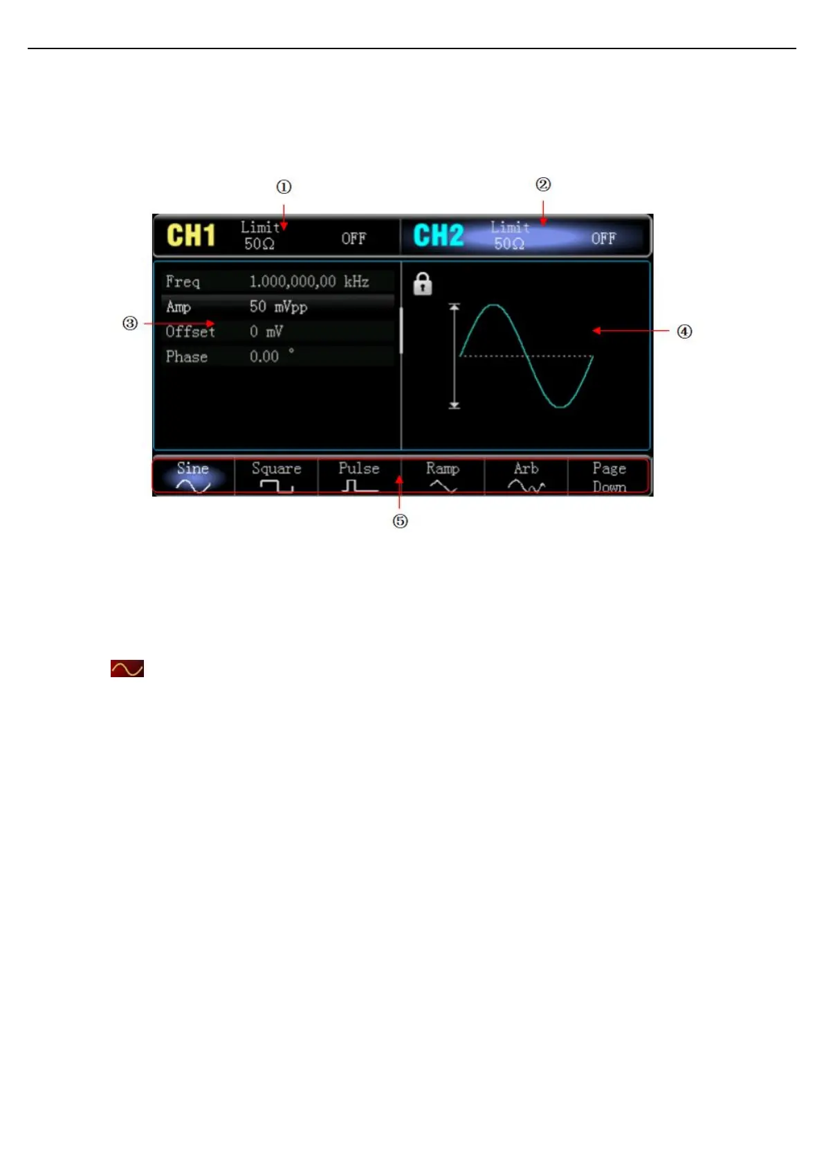
2.3.3 Function Interface
As shown in the following figure,
1. CH1 info, the currently selected channel will be highlighted.
“50Ω” indicates the impedance 50Ω to be matched at the output port(1Ω to 999Ω can be adjustable, or high
impedance, the factory default is Highz.)
“ ” indicates the current mode is sine wave. (In different working modes, it may be "fundamental wave ",
"modulation", "linear", "logarithmic" or "OFF".)
2. CH2 info is the same as CH1.
3. Wave parameter list: Display the parameter of the current wave in a list format. If an item indicates pure whit
in the list, then it can be set by the menu soft key, numerical keyboard, arrow keys and multifunction knob. If
the bottom color of the current character is the color of the current channel (it is white when the system is in
setting), it means that this character enters the editing state and the parameters can be set with the arrow
keys or numeric keyboard or multifunction knob.
4. Wave Display Area: Display the current wave of the channel (it can distinguish the current belongs to which
channel by the color or CH1/CH2 info bar, the wave parameter will display in the list at the left side.)
Notes: There is no wave display area when the system is set up. This area is expanded into a list of parameters.
5. Soft Key Label: To identify the function menu soft key and the menu operation soft key.
Highlight: It indicates that the right center of the label displays the color of the current channel or the gray
when the system is in setting, and the font is pure white.
 Loading...