29
Installation instructions
ENGLISH
( * )
If the storage tank temperature sensor is connected, DHW ser-
vice is automatically activated on boiler power supply.
Parameter (803) Srv (is automatically updated).
( ** )
Relay contact that closes when in alarm mode
( *** )
SHC optional
The system can power only one SHC module.
If you need to have more than one SHC module, they must be
placed externally in a dedicated electrical panel and
powered with their own power supply unit.
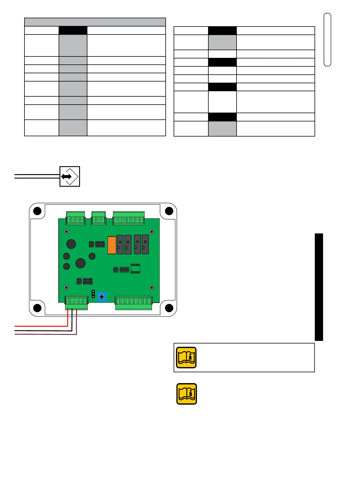
Connections for:
Y2 BCM
Modbus BCM
A
B
1
2
Remote boiler control
A (1) Data connection
B (2) Data connection
P. mod 4 - 5 Modulating heating pump
SE 6 - 7 External sensor
- / + 6 - 7 0 / 10 V signal contact
Stemp ACC
( * )
6 - 8 Storage Tank Temperature
Sensor
FL FL - 10 Flow switch (remove jumper)
INAIL 11-12 Safety devices
(remove jumper)
TA TA - 9 Room thermostat / Clock
remove jumper
678910 11 12 FL TA
Y2 - BCM
12345
FL
SE
TA
Alarm
signal
+
(+) 0-10V
(-) GND
P.
Mod.
C.P. M.
Alim.
230V
Stemp.
ACC
P.
Coll.
P.
CH
P. Car.
DHW
1
2
3
Y5
0
1
2
3
4
5
6
7
8
9
2
3
4
Y3
1
2
3
4
1
5
6
7
Y4
5
4
3
2
1
7
6
5
8
4
3
2
Y2
Y1
1
J1P
SHC
Modbus
INAIL
SAFE
INPUT 0-10V
1
Y3 -BCM
Y2 -HSCP/UFLY
56
843
Y1 -BMM1
432 1
Y4 -BCM
23
INAIL
Modbus
BCM
Ufly
Y4 - BCM
Alarm signal
(**)
3 - 4 Alarm / signal contact
(NO potential-free contact)
P. Coll. 1 - 2 Manifold pump (primary loop)
Y3 - BCM
P. CH 1 - 3 Heating circuit pump
P. Car DHW 1 - 2 Storage Tank loading Pump
Y2 -
UFLY
Modbus Uy
A
B
5
6
Remote Temperature
Control
A (5) Data connection
B (6) Data connection
Y1 BMM1
SHC
(***)
8 - 4 - 3 Optional multifunction module
(to be inserted in the box cover)
The BCM and SHC relay contacts support
pumps with max. 4A absorption.
Modbus BCM
can be used for control from building automation,
can also be connected
with Modbus Uy to have a single bus.