31
Installation instructions
ENGLISH
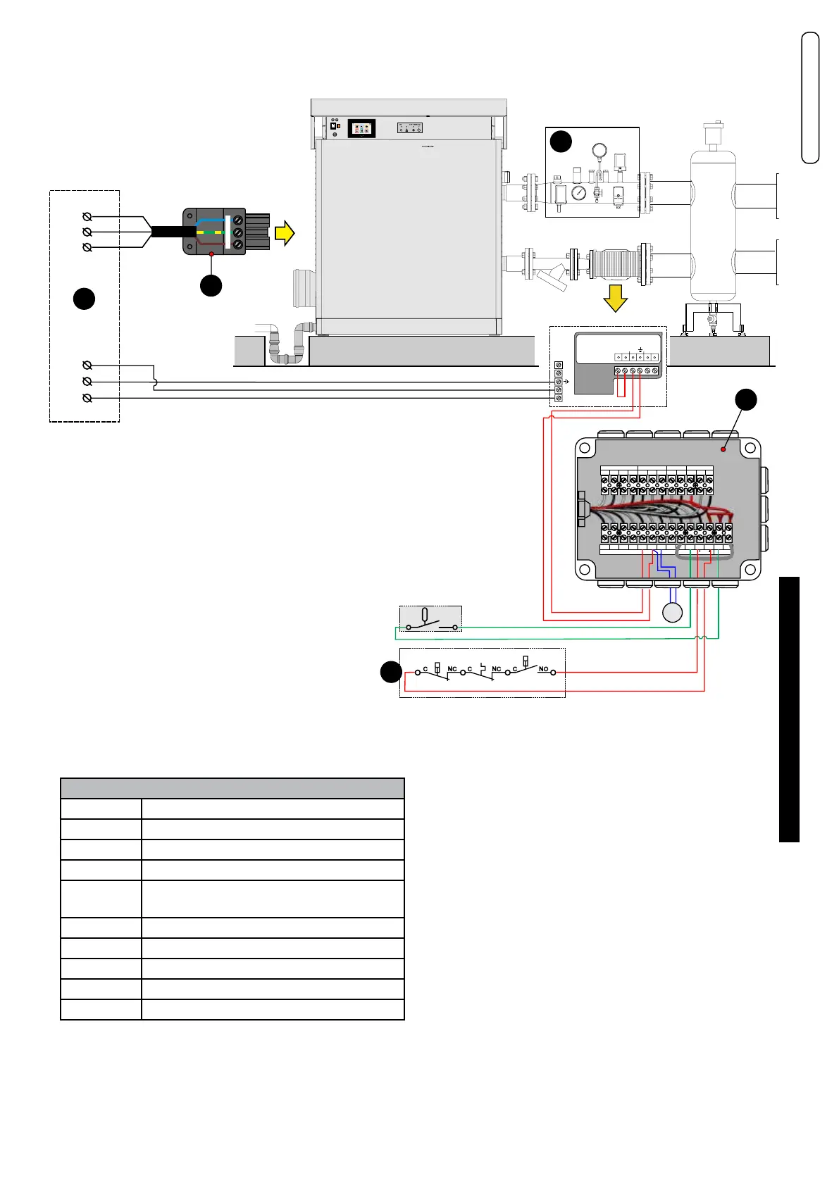
Connection diagram example:
Power supply, INAIL, Modulating pump, External sensor, Flow switch
D
230 V - 50 Hz
L1
PE
N
2
L1
PE
N
1
NPEL1
L
N
SS
M
Ext. MinDPIn
0-10V
P.
mod.
FL
1
C C CNC NC NO
1.3 (T.S.)
1.2 (P. min.)1.1 (P. max.)
SAFE
678910 11 12 FL TA
INAIL
Y2 -BCM
12345
1
Y3 - BCM
Y2 -HSCP/UFLY
56
843
Y1 -BMM1
432 1
Y4 - BCM
23
SE
Menu
B
KEY
No. Description
1 INAIL - Safety bodies
2 Main electrical panel (not supplied)
B Services connection return terminal board
D Wieland mobile pow. supp. socket 230 V -
50Hz
FL Terminals for Flow switch
SE Terminals for external Sensor
SMG Global ow sensor
P on_o Manifold Pump Connections (on_o)
P mod Modulating pump Connections